Biostar GF7050V-M7 Setup Manual - Page 5
Rear Panel Connect Ors - windows 7
 |
View all Biostar GF7050V-M7 manuals
Add to My Manuals
Save this manual to your list of manuals |
Page 5 highlights
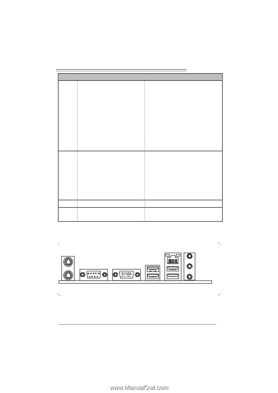
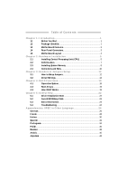
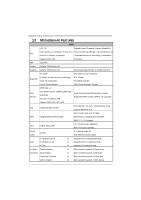
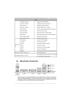
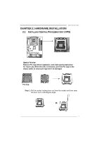
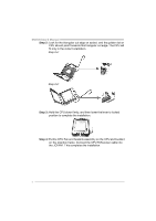
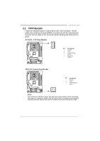
Front Panel Connector Front Audio Connector CD-in Connec tor S/PDIF out connector CPU Fan header System Fan header Clear CMOS header USB connector Power Connector (24pin) Power Connector (4pin) PS/2 Keyboard PS/2 Mouse Back Panel I/O Serial Port VGA port LAN port USB Port Audio Jack BoardSize 185 (W) x 244 (L) mm OS Support Windows XP / VISTA GF7050V-M7 SPEC x1 Supports front panel facilities x1 Supports front panel audio function x1 Supports CD audio-in function x1 Supports digital audio out function x1 CPU Fan power supply (with Smart Fan function) x1 System Fan Power supply x1 Restore CMOS data to factory default x2 Eachconnector supports 2 front panel USB ports x1 Connects to Power supply x1 Connects to Power supply x1 Connects to PS/2 Keyboard x1 Connects to PS/2 Mouse x1 Provide RS-232Serial connection x1 Connects to monitor. x1 Connects to RJ-45 ethernet cable x4 Connects to USB devices x3 Provide Audio-In/Out and microphone connection Micro ATX form Factor Biostar Reserves the right to add or remove support for any OS with or without notice. 1.4 REAR PANEL CONNECT ORS P S/ 2 M ouse PS / 2 Key board C OM 1 LAN V GA 1 USBX2 USBX2 Lin e In/ Surr ound Line Out Mic In 1/ Bas s/ Center Since the audio c hip s upports High Definiti on Audio Specific ation, the func tion of eac h audi o jack c an be defined by software. T he input / output function of each audio jac k listed above represents the default s etti ng. However, when c onnecti ng exter nal microphone to the audio port, pleas e us e the Line In (Blue) and Mic In (Pi nk) audio j ac k. 3
-
 1
1 -
 2
2 -
 3
3 -
 4
4 -
 5
5 -
 6
6 -
 7
7 -
 8
8 -
 9
9 -
 10
10 -
 11
11 -
12
-
13
-
14
-
15
-
16
-
17
-
18
-
19
-
20
-
21
-
22
-
23
-
24
-
25
-
26
-
27
-
28
-
29
-
30
-
31
-
32
-
33
-
34
-
35
-
36
-
37
-
38
-
39
-
40
-
41
-
42
-
43
-
44
-
45
 |
 |