Bosch DHR-1600A-150A User Manual - Page 15
Mouse Controls
 |
View all Bosch DHR-1600A-150A manuals
Add to My Manuals
Save this manual to your list of manuals |
Page 15 highlights
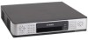
Divar XF 3.1.2 3.2 Operating instructions | en 15 Stop key - while in playback mode, press to return to live mode Note: IP camera numbering starts at 9 on an 8-channel model and at 17 on a 16-channel model. So on a 16-channel unit with IP cameras, camera key 1 selects analog camera 1 and IP camera 17. Indicators The indicators on the front panel display light or flash to alert you of various operating conditions. Power - lights when the unit is powered DVD- lights when a DVD is in the unit USB - lights when a USB memory device is connected to the unit Network - lights when a remote user is connected to the unit Record - lights when the unit is recording video Playback - lights when the unit is in playback mode Monitor A - indicates monitor A is being controlled Monitor B - indicates monitor B is being controlled Temperature - flashes when internal temperature is outside operational range Alarm - flashes when an alarm is detected Motion - flashes when motion is detected in a video signal Video loss - flashes when video loss is detected for a video input System failure - flashes when a system failure is detected Mouse Controls All functions controlled by the front panel can, alternatively, be accessed using the supplied USB mouse. All main DVR functions are accessible via the on-screen button panel. To display the panel (monitor A only), move the mouse pointer to the bottom left of the screen. Press ESC to remove it from the screen. Figure 3.2 On-screen button panel The buttons and indicators of the on-screen button panel work the same as the keys and indicators on the front panel. Bosch Security Systems User manual F.01U.135.431 | 2.5 | 2009.08
-
 1
1 -
2
-
3
-
4
-
5
-
6
-
7
-
8
-
9
-
 10
10 -
 11
11 -
 12
12 -
 13
13 -
 14
14 -
 15
15 -
 16
16 -
 17
17 -
 18
18 -
 19
19 -
 20
20 -
21
-
22
-
23
-
24
-
25
-
26
-
27
-
28
-
29
-
30
-
31
-
32
 |
 |
