Bosch HDI8056U Installation Instructions 1 - Page 7
Procedure
 |
View all Bosch HDI8056U manuals
Add to My Manuals
Save this manual to your list of manuals |
Page 7 highlights
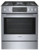
Procedure Replace Cooktop Orifices Convert Pressure Regulator from 6" W.C. to 11" W.C. 1. Remove warming drawer; pull drawer out until stop is reached. Facing the range, push clip on left side up and clip on right side down. Pull drawer the rest of the way out. 2. Remove cover plate from interior back wall by removing single screw on left side of panel. Use a torx T-20 head screwdriver. 3. Remove the hexagon cap from the top of the regulator with an adjustable wrench. 4. Pop out the plastic stem in the cap and turn it over pressing it firmly in place so that the letters "LP" (rather than "NAT") are seen upright in the stem. Replace the cap and button assembly into the top of the regulator sealing it firmly. Make certain spring is still in place (See Fig. 1). DO NOT OVERTIGHTEN. Pin Position for Nat. Gas Hex Cap NA Pin NAT T Pin Position for Propane Hex Cap Pin LP LP Spring PRESSURE REGULATOR VIEW Figure 1: Pressure Regulator 5. Fill out and affix the CONVERSION STICKER on the back side of the cover plate so that it appears on the back side of range next to the regulator. 1. Remove grates, burner caps and burner bases. Unscrew two (2) T20 screws inside each base and remove burner bases. Reinsert screws in jet holder to hold tubing assembly in place. Burner Grate Burner Cap Burner Base Orifice Ignitor Figure 2: Sealed Gas Burners 2. Remove natural gas cooktop orifices. Insert the socket driver with 3" minimum extension into the jet holders to remove existing orifices. Set natural gas orficies aside. 3. Assemble LP cooktop orifices. Place in cooktop exactly as specified on the orifice card. Placement can be determined by matching the orifice size to the number on the card. 4. Place the new orifice into the socket then insert each orifice into its respective threaded hole in the jet holder. Tighten until the orifice stops turning. DO NOT OVERTIGHTEN. 5. Remove screws placed in jet holder to replace burner base, burner cap and burner grate. Reinstall screws. Note: Burner cap must be properly positioned on burner base for burner to light. Correct Burner Cap Placement Incorrect Burner Cap Placement Burner Cap Placement 6. Retain natural gas orifices for future conversion back to natural gas. English 4
-
 1
1 -
 2
2 -
 3
3 -
 4
4 -
 5
5 -
 6
6 -
 7
7 -
 8
8 -
 9
9 -
 10
10 -
 11
11 -
 12
12 -
13
-
14
-
15
-
16
-
17
-
18
-
19
-
20
-
21
-
22
-
23
-
24
-
25
-
26
-
27
-
28
-
29
-
30
-
31
-
32
-
33
-
34
-
35
-
36
 |
 |
