Bosch KBE-495V28-20N Instruction Manual - Page 14
Housing, Line Power and Video Signal Connection, Connections for U Suffix, F Suffix, and N Suffix - 20
 |
View all Bosch KBE-495V28-20N manuals
Add to My Manuals
Save this manual to your list of manuals |
Page 14 highlights
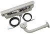
2 en | Installation 3.4 3.5 3.6 3.6.1 KBE and KBN Series Housing Feed the cabling from the housing foot through the mount. Attach the housing to the mount using the two (2) 1/4-20 screws and washers provided in the hardware kit. For additional information, refer to the LTC 9215/00 Mount Installation Manual and UHO-HBGS-10 Series Housing Installation Manual. Line Power and Video Signal Connection The external video coax cable is equipped with a female BNC connector for transmission of video. Route and connect video cable to the BNC connector. The external power cable is provided to allow for necessary stripping/preparation by the installer. For additional information, refer to the Installation Manuals included in the Instruction Booklet Packet. Color Green White Black Connection Ground 24 V 24 V Connections for U Suffix, F Suffix, and N Suffix The connections for models containing fiber optic, network, or twisted pair interfaces are covered as follows: U (Twisted Pair) Suffix Connections These models include an unshielded twisted pair transmitter added to the standard construction. 1. Make all power connections in accordance with the KBE and KBN Series Instruction Manual. 2. Pass the supplied orange string through the mounting foot of the camera housing and the furnished mount. See Figure 3.2. A fitting may be used in the mounting foot if desired. 3. Attach the end of the string to the unshielded twisted pair (UTP) video cable and pull it through the mount and the unused hole in the mounting foot of the camera housing as shown in Figure 3.3. 4. Connect the UTP video cable to the the -VID+ pins on UTP transmitter. Observe polarity; the video connection is polarity-sensitive. See Figure 3.1. Figure 3.1 Connecting the UTP Cable to the Transmitter Reference 1 2 Description Negative (-) terminal for twisted pair video lead Positive (+) terminal for twisted pair video lead 5. Seal the hole in the mounting foot of the camera housing with RTV or an equivalent seal. If a fitting was used in the mounting foot, apply the seal around the UTP cable before tightening the fitting to prevent slippage. F01U065975 | 1.0 | 2007.04 Instruction Manual Bosch Security Systems, Inc.
-
 1
1 -
2
-
3
-
4
-
5
-
6
-
7
-
8
-
 9
9 -
 10
10 -
 11
11 -
 12
12 -
 13
13 -
 14
14 -
 15
15 -
 16
16 -
 17
17 -
 18
18 -
 19
19 -
20
-
21
-
22
-
23
-
24
 |
 |
