Brother International BAS-326G PS Basic Instruction Manual - English - Page 19
Connecting the cords, INSTALLATION, <Main P.C. board>
 |
View all Brother International BAS-326G PS manuals
Add to My Manuals
Save this manual to your list of manuals |
Page 19 highlights
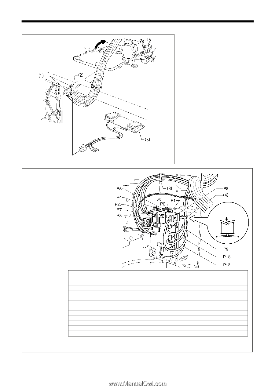
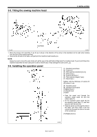
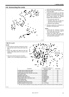
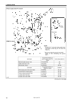
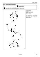
3-8. Connecting the cords NOTE: • Check that the connector is facing the correct way, and then insert it firmly until it locks into place. • Secure the cables with cable ties and cord clamps, while being careful not to pull on the connector. *1 : Be sure to make the ground connection. (Refer to "3-9. Connecting the ground wire".) 3. INSTALLATION 1. Gently tilt back the machine head. 2. Pass the cord bundle through the hole in the work table. 3. Loosen the two screws (1), and then open the cord presser plate (2) in the direction of the arrow and pass the cord bundle through the opening together with the following cords. • Two-pedal foot switch (3) • Operation panel (Do not pass the ground wires through the hole.) • Solenoid valve assembly 4. Securely connect the connectors as indicated in the table below. NOTE: • Check that the connector is facing the correct way, and then insert it firmly until it locks into place. • Secure the cables with cable ties and cord clamps, while being careful not to pull on the connector. 2147B Lock the cord clamp securely. 2148B Connector Connection location on main P.C. board Cord clamp X pulse motor encoder 5-pin white P20 (X-ENC) (3) Y pulse motor encoder 5-pin blue P4 (Y-ENC) (3) Work clamp pulse motor encoder 5-pin black P5 (P-ENC) (3) Foot switch 10-pin P6 (FOOT) (3) Operation panel 8-pin P1 (PANEL) (3) Machine head switch 3-pin P9 (HEAD-SW) (4) Home position sensor assembly 12-pin P8 (SENSOR1) (4) STOP switch 6-pin P13 (HEAD) (4) Valve harness 12-pin P12 (AIR1) (4) Programmer relay harness 8-pin Solenoid selection harness 4-pin*2 P7 (PRG) (3) P3(CUTTER) - *2 : The 4-pin solenoid selection harness may not be used for some versions of tension release solenoid. BAS-326G PS 11
-
 1
1 -
2
-
3
-
4
-
5
-
6
-
7
-
8
-
9
-
10
-
11
-
12
-
13
-
 14
14 -
 15
15 -
 16
16 -
 17
17 -
 18
18 -
 19
19 -
 20
20 -
 21
21 -
 22
22 -
 23
23 -
 24
24 -
25
-
26
-
27
-
28
-
29
-
30
-
31
-
32
-
33
-
34
-
35
-
36
-
37
-
38
-
39
-
40
-
41
-
42
 |
 |