Brother International MFC 665CW Quick Setup Guide - English - Page 8
Connecting the phone line, Improper Setup - user manual
 |
UPC - 012502615811
View all Brother International MFC 665CW manuals
Add to My Manuals
Save this manual to your list of manuals |
Page 8 highlights
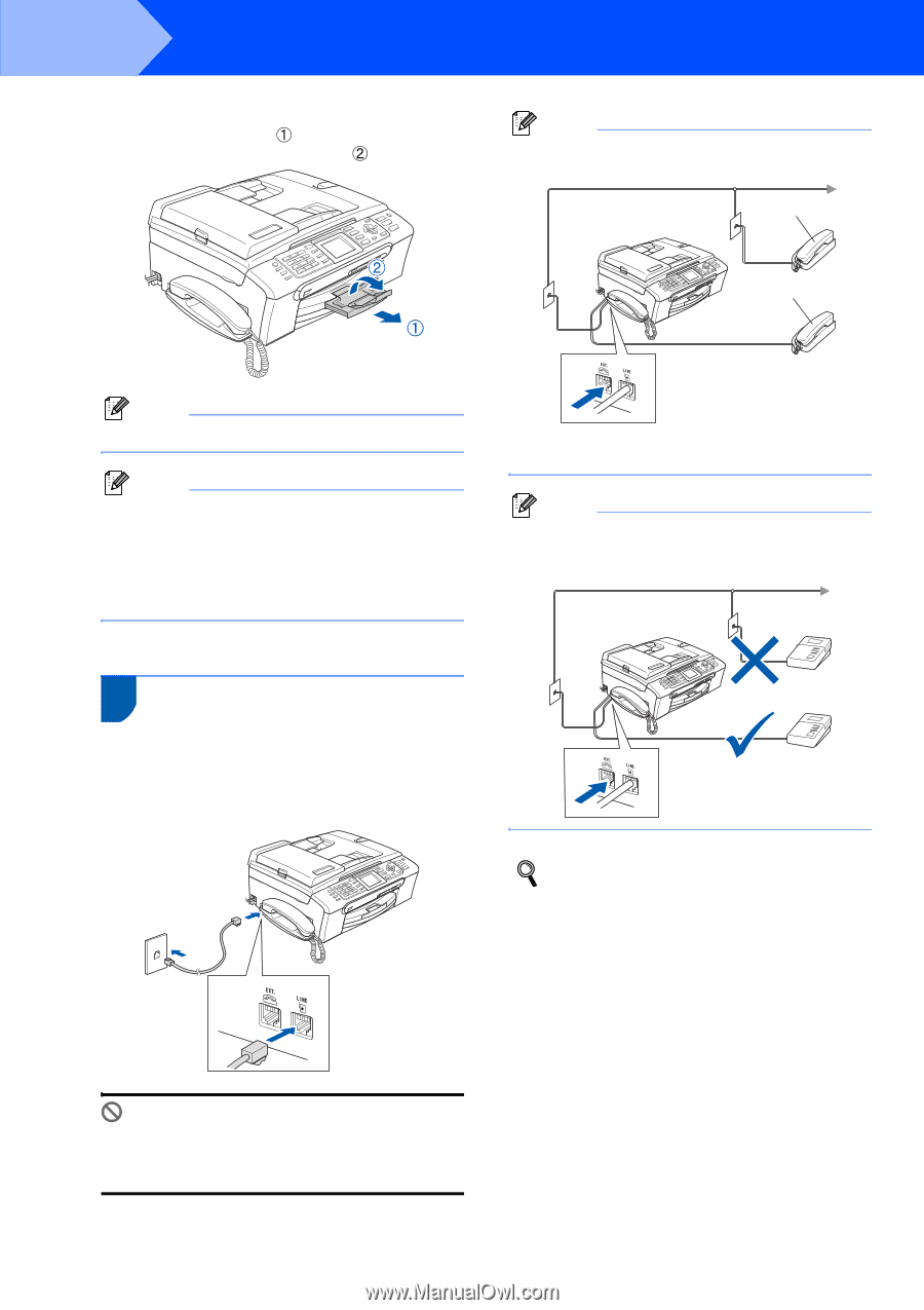
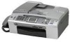
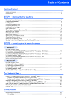
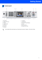
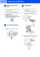
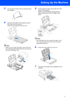
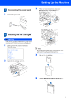
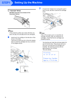
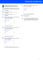
STEP1 Setting Up the Machine 8 While holding the paper tray in place, pull out the paper support ( ) until it clicks, and then unfold the paper support flap ( ). Note If you are sharing one phone line with an external telephone, connect it as shown below. 1 2 Note Do not use the paper support flap for Legal paper. Note • You can use the photo bypass tray which is located on the top of the paper tray to print on photo 4 x 6 in. (10 x 15 cm) and photo L size paper. • For details, see Loading photo paper in Chapter 2 of the User's Guide. 1 Extension telephone 2 External telephone Note If you are sharing one phone line with an external telephone answering machine, connect it as shown below. 4 Connecting the phone line 1 Connect the telephone line cord. Connect one end of the telephone line cord to the jack on the machine marked LINE and the other end to a modular wall jack. Set the receive mode to 'Manual' if you have an external answering machine. For details, see Connecting an external TAD (telephone answering device) in Chapter 7 of the User's Guide. Improper Setup DO NOT connect the interface cable. Connecting the interface cable is done during the software installation process. 6
-
 1
1 -
2
-
 3
3 -
 4
4 -
 5
5 -
 6
6 -
 7
7 -
 8
8 -
 9
9 -
 10
10 -
 11
11 -
 12
12 -
 13
13 -
14
-
15
-
16
-
17
-
18
-
19
-
20
-
21
-
22
-
23
-
24
-
25
-
26
-
27
-
28
-
29
-
30
-
31
-
32
-
33
-
34
-
35
-
36
-
37
-
38
-
39
-
40
-
41
-
42
-
43
-
44
-
45
-
46
-
47
-
48
-
49
-
50
-
51
-
52
-
53
-
54
-
55
-
56
-
57
 |
 |