Brother International MFC 9060 Service Manual
Brother International MFC 9060 - B/W Laser - All-in-One Manual
 |
UPC - 012502040064
View all Brother International MFC 9060 manuals
Add to My Manuals
Save this manual to your list of manuals |
Brother International MFC 9060 manual content summary:
- Brother International MFC 9060 | Service Manual - Page 1
FACSIMILE EQUIPMENT SERVICE MANUAL MODEL: FAX2600/FAX-8060P MFC4300/MFC4600/ MFC-9060 - Brother International MFC 9060 | Service Manual - Page 2
© Copyright Brother 2000 All rights reserved. No part of this publication may be reproduced in any form or by any means without permission in writing from the publisher. Specifications are subject to change without notice. - Brother International MFC 9060 | Service Manual - Page 3
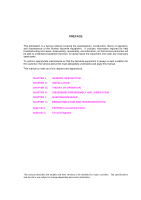
This publication is a Service Manual covering the specifications, construction, theory of operation, and maintenance of the Brother facsimile equipment. It includes information required for field troubleshooting and repair--disassembly, reassembly, and lubrication--so that service personnel will be - Brother International MFC 9060 | Service Manual - Page 4
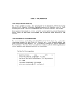
1968. This means that the printer does not produce hazardous laser radiation. Since radiation emitted inside the printer is completely confined within the protective housings and external covers, the laser beam cannot escape from the machine during any phase of user operation. CDRH Regulations (110 - Brother International MFC 9060 | Service Manual - Page 5
CHAPTER I. GENERAL DESCRIPTION - Brother International MFC 9060 | Service Manual - Page 6
CHAPTER I. GENERAL DESCRIPTION CONTENTS 1. EQUIPMENT OUTLINE I-1 1.1 External Appearance and Weight I-1 1.2 Components ...I-1 2. SPECIFICATIONS...I-2 - Brother International MFC 9060 | Service Manual - Page 7
1.1 External Appearance and Weight The figure below shows the equipment appearance and approximate dimensions. Weight: Machine proper Machine (incl. drum unit & toner cartridge) In package 1.2 Components The equipment consists of the following major components: Approx. 7.2 kg Approx. 8.5 kg - Brother International MFC 9060 | Service Manual - Page 8
FAX Yes Yes Yes Modem Speed (bps) 14.4K (FAX Only) 14.4K (FAX Only) 14.4K (FAX SL/Auto/SD SL/Auto/SD FAX/TEL Switch Yes Yes Yes Distinctive Yes Yes Yes Next FAX Reservation Yes - Dual Access Yes Paging Yes Yes Yes FAX Forwarding Yes Yes Yes FAX Retrieval Yes Yes Yes - Brother International MFC 9060 | Service Manual - Page 9
1.3 MB (up to 130 pages: MMR) Call Back Message Yes *1 Call Waiting Caller ID is not available. *2 According to the Brother chart in standard mode, MMR. (1/3) MFC9060 Gray 1495 Yes 14.4K (FAX Only) G3 MH/MR/MMR Yes 6 64 Yes Yes Yes 8.5" x 8.5" 20 16 x 1 No No 16 (8x2) 30 Yes Yes SL - Brother International MFC 9060 | Service Manual - Page 10
PRINTER Engine/Type PPM DPI (output resolution) Paper Capacity Emulation (Standard) Standards Memory (Typical) Memory (MIN.) Fonts Resident Fonts Disk Based Paper Handling Multi-Purpose Tray Toner Life (Starter) Toner Life (Supply) Drum Life Utility Software - Windows GDI (600 x 600) Windows GDI - Brother International MFC 9060 | Service Manual - Page 11
(DL/C5/CM10/Mona) Support Windows OS (Printer Driver) - Windows95/98 and NT4.0/2000 Driver with Auto Installer Program Toner Life (Standard) 1,000 pages with 5% black 1,000 pages with 5% black Toner Life (Supply) 2,200 pages with 5% black 2,200 pages with 5% black Drum Life 20,000 pages - Brother International MFC 9060 | Service Manual - Page 12
Yes (PRINTER/FAX, PRINTER/COPY) Yes Yes 2MB N/A Yes (PRINTER/FAX, PRINTER/SCAN, PRINTER/COPY) Yes Windows3.1x/95/98/ME, NT 4.0/2000 Driver with Auto Installer Program No Windows3.1x/95/98/ME, NT 4.0/2000 Driver with Auto Installer Program Yes (Brother) No No No Yes (Brother) Yes (Brother) Yes - Brother International MFC 9060 | Service Manual - Page 13
Yes Memory Backup No Memory Security No Pin TX LOCK Yes Bundled Software N/A Applications Printer Driver - PC-FAX (Send/Receive) - Scanner Application - Viewer Application - Network Application No Class1 No (3/3) MFC9060 Yes 203 x 391 99 50, 75, 87, 93, 100, 120, 125, 150 - Brother International MFC 9060 | Service Manual - Page 14
CHAPTER II. INSTALLATION - Brother International MFC 9060 | Service Manual - Page 15
CHAPTER II. INSTALLATION CONTENTS 1. INSTALLING THE UPDATE DATA TO THE FACSIMILE EQUIPMENT II-1 - Brother International MFC 9060 | Service Manual - Page 16
interface port on the back of the equipment and secure it with the lock wires. (4) Connect the other end of the interface cable to the printer port of your computer and secure it with the two screws. (5) Power on your computer. (6) Plug the equipment's power cord into a wall socket. Interface cable - Brother International MFC 9060 | Service Manual - Page 17
point to Programs, and then click MS-DOS Prompt to open an MS- DOS window. (3) Type the drive letter where the update data and transfer utility are located. the ENTER key. During downloading, the equipment beeps intermittently. Upon completion of the downloading, the equipment beeps continuously. - Brother International MFC 9060 | Service Manual - Page 18
CHAPTER III. THEORY OF OPERATION - Brother International MFC 9060 | Service Manual - Page 19
1. OVERVIEW ...III-1 2. MECHANISMS ...III-2 2.1 Scanner Mechanism III-3 2.1.1 Document feeding and ejecting mechanism III-3 2.1.2 Scanner...III-3 2.2 Laser Printing Mechanism III-4 2.2.1 Paper pulling-in, registration, feeding, and ejecting mechanism III-4 2.2.2 Print process mechanism III - Brother International MFC 9060 | Service Manual - Page 20
1. OVERVIEW *Not provided on the FAX8060P/MFC9060. III - 1 - Brother International MFC 9060 | Service Manual - Page 21
equipment is classified into the following mechanisms: SCANNER MECHANISM - Document feeding and ejecting mechanism - Document scanning mechanism LASER PRINTING MECHANISM - Paper pulling-in, registration, feeding, and ejecting mechanisms - Print process mechanism (consisting of charging, exposing - Brother International MFC 9060 | Service Manual - Page 22
the document stacker and starts the scanning operation, the scanner motor rotates so that the ADF (which consists of the separation roller and ADF parts) feeds those documents into the equipment, starting from the bottom sheet to the top, page by page. Each document advances with the document feed - Brother International MFC 9060 | Service Manual - Page 23
2.2 Laser Printing Mechanism 2.2.1 Paper pulling-in, registration, feeding, and ejecting mechanism III - 4 - Brother International MFC 9060 | Service Manual - Page 24
the registration roller. Paper feeding and ejecting mechanism If the main motor rotates clockwise, the rotation is transmitted via the gear train to the drum drive gear, heater roller drive gear, and paper ejection roller drive gear. After the paper passes through the heat-fixing process, it will be - Brother International MFC 9060 | Service Manual - Page 25
2.2.2 Print process mechanism The print process unit works with laser beam, electrical charges, and toner. The graph below shows the transition of electrical charge on the surface of the laser-sensitive drum through the five processes: charging, exposing, developing, transferring, and erasing - Brother International MFC 9060 | Service Manual - Page 26
2.2.3 Heat-fixing mechanism As the paper passes between the heater roller and the pressure roller in the heat-fixing unit, the heater roller fuses the toner on the paper. III - 7 - Brother International MFC 9060 | Service Manual - Page 27
PCB Toner sensor PCB Toner sensor PCB Heat-fixing unit Hook switch PCB* *Not provided on the FAX8060P/MFC9060. jam. • Paper ejection sensor which detects whether the recording paper goes out of the equipment. • Toner sensor which detects whether there is toner or a toner cartridge is loaded. • Toner - Brother International MFC 9060 | Service Manual - Page 28
*Not provided on the FAX8060P/MFC9060. Location of Sensors and Actuators III - 9 - Brother International MFC 9060 | Service Manual - Page 29
3. CONTROL ELECTRONICS 3.1 Configuration The hardware configuration of the facsimile equipment is shown below. (NOTE 1) Not provided on the FAX2600/FAX8060P (NOTE 2) Provided on the European, Australian, Indonesian, and Asian versions. Configuration of Facsimile Equipment III - 10 - Brother International MFC 9060 | Service Manual - Page 30
CHAPTER IV. DISASSEMBLY/REASSEMBLY AND LUBRICATION - Brother International MFC 9060 | Service Manual - Page 31
Option Cover IV-5 1.2 Multi-purpose Sheet Feeder IV-6 1.3 Document Guide Base IV-7 1.4 Control Panel ASSY IV-8 1.5 Panel Rear Cover FAX8060P/MFC9060) Side Cover (for FAX8060P/MFC9060 IV-23 1.10 Heat-fixing Unit, FU Lamp, and Paper Ejection Sensor Actuator IV-25 1.11 Laser Unit and Toner Sensor - Brother International MFC 9060 | Service Manual - Page 32
2. LUBRICATION ...IV-44 [ 1 ] Document feed roller ASSY and document ejection roller ASSY IV-44 [ 2 ] Control panel locks IV-45 [ 3 ] Scanner frame ASSY and separation roller gear IV-45 [ 4 ] Top cover lock spring IV-46 [ 5 ] Gear drive unit IV-46 ii - Brother International MFC 9060 | Service Manual - Page 33
When servicing the optical system of the laser printing unit, be careful not to place screwdrivers or other reflective objects in the path of the laser beam. Be sure to take off any personal accessories such as wrist watches and rings before working on the printer. A reflected - Brother International MFC 9060 | Service Manual - Page 34
Location Screw type Q'ty Option cover Screw, pan (washer) M3x8DB 2 ADF parts Panel rear cover Taptite, pan (washer) B M3x6 1 Taptite, cup Taptite, cup B M3x10 2 Heat-fixing unit Taptite, bind B M4x12 1 Laser unit Toner sensor PCB Taptite, bind B M4x12 3 Taptite, cup B M3x8 1 - Brother International MFC 9060 | Service Manual - Page 35
the paper tray, and - the drum unit (with the toner cartridge loaded) (*Not provided on the FAX8060P/MFC9060) How to Access the Object Component need to remove parts numbered , , , , , and so as to access the gear drive unit. • Unless otherwise specified, the disassembled parts or components should - Brother International MFC 9060 | Service Manual - Page 36
Disassembly Order Flow IV - 4 - Brother International MFC 9060 | Service Manual - Page 37
1.1 ROM Cover and Option Cover (1) As shown below, push down section "a" of the ROM cover and tilt it to the rear. (2) Take off the option cover from the rear of the main cover by removing two screws "a." The grounding wire also comes free. IV - 5 - Brother International MFC 9060 | Service Manual - Page 38
1.2 Multi-purpose Sheet Feeder (1) Open the top cover. (2) Remove one of two screws from each of right and left top cover stoppers, and then fully open the top cover. (3) Pull either one of the right and left tabs provided on the main cover outwards and slightly lift up the multi-purpose sheet - Brother International MFC 9060 | Service Manual - Page 39
1.3 Document Guide Base (1) Turn up the document guide base towards you. (2) Push the right or left end of the document guide base inwards and take it off. IV - 7 - Brother International MFC 9060 | Service Manual - Page 40
1.4 Control Panel ASSY (1) Slightly open the control panel ASSY. (2) Push the right and left arms of the control panel ASSY outwards (in the direction of arrow ) with your thumbs and open the control panel ASSY further (arrow ) to unhook those arms from bosses "x" provided on the scanner frame ASSY. - Brother International MFC 9060 | Service Manual - Page 41
, remove them. NOTE: Once removed, the anti-static brush and shield film will become unusable and new parts will have to be put back in. (4) To remove the document pressure bar, pull either of supports "a" provided on the panel rear cover outwards and then lift the pressure bar up and towards the - Brother International MFC 9060 | Service Manual - Page 42
(6) Remove the two screws from the panel rear cover. (7) Unhook the panel rear cover from eight "X" latches provided on the control panel and lift up the panel rear cover. (8) Fully turn the document front sensor actuator to the rear and lift it up. (9) Unhook the document sensor PCB from two "Y" - Brother International MFC 9060 | Service Manual - Page 43
and requires replacement. Reassembling Notes • Before reinstalling the LCD to the control panel, wipe fingerprints or dust off the LCD surface and control panel window with a soft cloth. • A new LCD is covered with a protection sheet. Before installing it, remove the protection sheet. IV - 11 - Brother International MFC 9060 | Service Manual - Page 44
1.6 Document Feed Roller ASSY and Document Ejection Roller ASSY (1) Lightly push down arm rib "a" and shift the document feed roller ASSY to the right and upwards. (2) Lightly push down arm rib "b" and shift the document ejection roller ASSY to the right and upwards, without removing the shield film - Brother International MFC 9060 | Service Manual - Page 45
1.7 Scanner Frame ASSY (1) You can remove the following parts from the top of the scanner frame ASSY without taking out the ASSY from the top cover. • CIS film • Shield film • CIS unit (shown on - Brother International MFC 9060 | Service Manual - Page 46
(2) Open the top cover. (3) Disconnect the scanner motor harness from the scanner motor ASSY without removing the shield film. IV - 14 - Brother International MFC 9060 | Service Manual - Page 47
(4) Close the top cover. (5) Remove the two screws from the scanner frame ASSY. (6) Lift up the rear edge of the scanner frame ASSY to release the three pawls provided on the front end from the top cover, then hold up the ASSY and disconnect the CIS harness (if the CIS is mounted). (7) Take off the - Brother International MFC 9060 | Service Manual - Page 48
(8) Turn the scanner frame ASSY upside down. (9) Remove the screw from the scanner motor and turn the motor clockwise to release from the latch. (10) Take off the scanner grounding leaf spring by removing the screw. (11) Take off the CIS shield plate by removing the screw. (12) Remove the pinch - Brother International MFC 9060 | Service Manual - Page 49
(14) Remove the pressure roller leaf springs by pulling them in the direction of arrows and in this order as shown below. Then remove the pressure rollers and shaft. (15) Slightly push down the arm (in the direction of arrow ) and shift the separation roller gear to the right (arrow ) when viewed - Brother International MFC 9060 | Service Manual - Page 50
(16) Take off the scanner drive unit by removing the two screws. The separation roller gear also comes off. (17) Push down the CIS side spring to release it from the latch, then pull it out to the right (when viewed from the rear). IV - 18 - Brother International MFC 9060 | Service Manual - Page 51
scanner motor harness to the scanner motor connector, take care not to bend the shield film. • Once removed, the shield film becomes unusable and a new part will have to be put back in. IV - 19 - Brother International MFC 9060 | Service Manual - Page 52
1.8 Top Cover (1) Open the top cover. (2) Remove one of two screws from each of right and left top cover stoppers, and then fully open the top cover. (3) Pull the panel-main harness and CIS harness towards you. (4) Remove the adhesive tape and pull the scanner motor harness and grounding wire - Brother International MFC 9060 | Service Manual - Page 53
(5) Remove the four screws from the hinges R and L. (6) Slightly lift up the top cover to release the bosses from the hinges and take it off to the rear. (7) Remove the harness support sponges and take out the harnesses from the top cover. IV - 21 - Brother International MFC 9060 | Service Manual - Page 54
hooks "A2" of the main cover, and then fix them with the support sponge. Route the panel-main harness and CIS harness through hooks "B1" through hooks "B2" of the main cover, and then fix them with the support sponge. • When connecting the scanner motor harness to the scanner motor connector, take - Brother International MFC 9060 | Service Manual - Page 55
1.9 Handset Mount and Hook Switch PCB (for models except FAX8060P/MFC9060) Side Cover (for FAX8060P/MFC9060) (1) Open the top cover. (2) Remove one of two screws from each of right and to the main PCB in the main cover. *For models except the FAX8060P/MFC9060 **For the FAX8060P/MFC9060 IV - 23 - Brother International MFC 9060 | Service Manual - Page 56
(5) Disassemble the handset mount by unhooking two latches "a" of the upper handset mount with a flat screwdriver. (6) Remove the hook switch PCB ASSY by unhooking latch "b." (7) Disconnect the hook switch harness from the hook switch PCB. Reassembling Notes • When assembling the upper and lower - Brother International MFC 9060 | Service Manual - Page 57
1.10 Heat-fixing Unit, FU Lamp, and Paper Ejection Sensor Actuator (1) Open the top cover. (2) Remove one of two screws from each of right and left top cover stoppers, then fully open the top cover. (3) Remove screw "a." (4) Lift the left end of the heat-fixing unit up and to the left to release the - Brother International MFC 9060 | Service Manual - Page 58
(6) To take out the FU lamp from the heat-fixing unit, remove two screws "b." (7) Unhook the two latches outwards with the tip of a small flat screwdriver and open the upper cover. (8) Fully open the upper cover and remove it. (9) Remove screw "d" and loosen screw "c." (10) Hold the lock plate of - Brother International MFC 9060 | Service Manual - Page 59
PCB and disconnect its harness. (3) Remove the three screws from the laser unit. (4) Slightly lift up the laser unit and disconnect the following from the main PCB: - Laser diode harness (5-pin) - Toner sensor harness (4-pin) if the toner sensor PCB is installed - Polygon motor flat cable NOTE: When - Brother International MFC 9060 | Service Manual - Page 60
1.12 Bottom Plate (1) Turn the facsimile equipment upside down. (2) Remove two screws "b" from the interface connector. (3) Remove seven screws "c" and three screws "d" from the bottom plate. (4) Slightly lift up the bottom plate, then take off the AC cord bushing and remove screw "e" from the - Brother International MFC 9060 | Service Manual - Page 61
Reassembling Notes • When putting the bottom plate into place, secure the grounding wire to the bottom plate with screw "e," fit the AC cord bushing into the cutout of the bottom plate, and fit the holes over the bosses of the main cover. First tighten screws "b" (interface connector screws) and - Brother International MFC 9060 | Service Manual - Page 62
the blue and brown wires) from the low-voltage power supply PCB. Reassembling Notes • Be sure to route the heater harness through the three wire guides as illustrated above. IV - 30 - Brother International MFC 9060 | Service Manual - Page 63
from the main PCB: • Speaker harness (2-pin, P7) • Laser diode harness (5-pin, P6) • Toner sensor harness (4-pin, P5) • Polygon motor flat cable (5-pin, Indonesian, and Asian versions.) (*2 Not provided on the FAX8060P/MFC9060.) Reassembling Notes • Route the hook switch harness (red), solenoid - Brother International MFC 9060 | Service Manual - Page 64
*1 Provided on the European, Australian, Indonesian, and Asian versions. *2 Not provided on the FAX8060P/MFC9060. IV - 32 - Brother International MFC 9060 | Service Manual - Page 65
Setting up the main PCB after replacement IV - 33 - Brother International MFC 9060 | Service Manual - Page 66
Notes • Before reinstalling the high-voltage power supply PCB, check the high-voltage contacts for any toner particles, paper dust or dirt, and clean them out. • Be sure to route the drum grounding harness through boss "x" and latches "y" and "z." • When putting the high-voltage power supply PCB - Brother International MFC 9060 | Service Manual - Page 67
main PCB (refer to Section 1.14). (2) Slightly lift up the main PCB and disconnect the fan harness from the main PCB. (3) Take out the fan support. (4) Pull up the fan. Reassembling Notes • Put the fan back into place with the non-sponge end facing up and with the label side facing - Brother International MFC 9060 | Service Manual - Page 68
1.17 Registration Sensor Actuator and Top Cover Sensor Actuator (1) Pull up the registration sensor actuator and top cover sensor actuator. 1.18 Speaker (1) Pull the speaker spring inwards and pull up the speaker. Reassembling Notes • Put the speaker into place with its harness facing to the front. - Brother International MFC 9060 | Service Manual - Page 69
1.19 Gear Drive Unit (1) Make sure that the heat-fixing unit is removed. (2) Remove the three screws from the gear drive unit. (3) Lift the gear drive unit up and out of the main cover. IV - 37 - Brother International MFC 9060 | Service Manual - Page 70
(4) To take off the main motor, remove two screws "x." (5) To take off the paper feed solenoid, solenoid lever, or clutch release lever, remove three screws "y." Main motor "x" Taptite, cup S M3x8 Motor bracket "y" Solenoid lever Clutch release lever Taptite, cup B M4x20 "y" Solenoid spring - Brother International MFC 9060 | Service Manual - Page 71
1.20 NCU PCB (1) Make sure that the MJ cover, low-voltage power supply PCB and gear drive unit are removed. (2) Remove the screw from the NCU bracket. (3) Slightly lift up the NCU bracket (which holds the NCU PCB) and then disconnect the NCU harness from the NCU PCB. (* Provided on the European, - Brother International MFC 9060 | Service Manual - Page 72
(4) Remove the screw and take off the NCU PCB from the NCU bracket. (* Provided on the European, Australian, Indonesian, and Asian versions.) Reassembling Notes • When setting the NCU PCB to the NCU bracket, fit its edges onto "b" and "c" and into "a" and "d" as illustrated above. • European, - Brother International MFC 9060 | Service Manual - Page 73
1.21 Scanner Grounding Plate (1) Make sure that the heat-fixing unit is removed. (2) Remove the screw from the scanner grounding plate and take it off. (If the bottom plate has not been removed, remove front screw "c" also (see page IV-28) that secures both the scanner grounding plate and bottom - Brother International MFC 9060 | Service Manual - Page 74
1.22 EL (Eraser Lamp) Board Only when you need to replace the EL board (which is attached with double-sided adhesive tape), remove it according to the steps below. (1) Make sure that the EL board harness is disconnected from the high-voltage power supply PCB. (Refer to Section 1.15.) (2) Make sure - Brother International MFC 9060 | Service Manual - Page 75
1.23 Cleaning of High-voltage Contacts and Grounding Contacts If any toner particles, paper dust or dirt are on the contacts, clean them out. This will ensure that power flows correctly to enable printing. Grounding contacts High-voltage contacts IV - 43 - Brother International MFC 9060 | Service Manual - Page 76
2. LUBRICATION Apply the specified lubricants to the lubrication points as shown below. Lubricant type (Manufacturer) Molykote EM-30LG or EM-30L (Dow Corning) Conductive grease FLOIL GE676 (Kanto Kasei Ltd.) Thin coat of grease (1 mm3) Lubricant amount Half of a rice-sized pinch of grease (3 mm3 - Brother International MFC 9060 | Service Manual - Page 77
[ 2 ] Control panel locks [ 3 ] Scanner frame ASSY and separation roller gear IV - 45 - Brother International MFC 9060 | Service Manual - Page 78
[ 4 ] Top cover lock spring [ 5 ] Gear drive unit IV - 46 - Brother International MFC 9060 | Service Manual - Page 79
CHAPTER V. MAINTENANCE MODE - Brother International MFC 9060 | Service Manual - Page 80
CHAPTER V. MAINTENANCE MODE CONTENTS 1. ENTRY INTO THE MAINTENANCE MODE V-1 2. LIST OF MAINTENANCE-MODE FUNCTIONS V-2 3. DETAILED DESCRIPTION OF MAINTENANCE-MODE FUNCTIONS V-4 3.1 EEPROM Parameter Initialization V-4 3.2 Printout of Scanning Compensation Data V-5 3.3 ADF Performance Test V-7 - Brother International MFC 9060 | Service Manual - Page 81
/MFC4300/MFC4600: To make the equipment enter the maintenance mode, press the Function, *, 2, 8, 6, and 4 keys in this order. Within 2 seconds FAX8060P/MFC9060: To make the equipment enter the maintenance mode, press the Menu, *, 2, 8, 6, and 4 keys in this order. Within 2 seconds The equipment - Brother International MFC 9060 | Service Manual - Page 82
2. LIST OF MAINTENANCE-MODE FUNCTIONS Function Code 01 02 03 04 05 06 07 08 09 10 11 12 13 14 15 32 74 82 87 91 99 Maintenance-mode Functions Function EEPROM Parameter Initialization Reference Subsection (Page) 3.1 (V-4) Printout of Scanning Compensation Data 3.2 (V-5) ADF* Performance Test - Brother International MFC 9060 | Service Manual - Page 83
which are shaded in the firmware switch tables in Subsection 3.5. The service personnel should instruct end users to follow the procedure given below. (1) FAX2600/MFC4300/MFC4600: Press the Function and Mode keys in this order. FAX8060P/MFC9060: Press the Menu and Mode keys in this order. The LCD - Brother International MFC 9060 | Service Manual - Page 84
the EEPROM areas, but entering 91 does not initialize some areas, as listed below. Data item Function code Maintenance-mode functions User switches Firmware switches Activity report Station ID data Remote activation code Outside line number Telephone function registration One-touch dialing Speed - Brother International MFC 9060 | Service Manual - Page 85
3.2 Printout of Scanning Compensation Data Function The equipment prints out the white and black level data for scanning compensation. Operating Procedure Do not start this function merely after powering on the equipment but start it after carrying out a sequence of scanning operation. Unless the - Brother International MFC 9060 | Service Manual - Page 86
a) b) c) d) Scanning Compensation Data List V - 6 - Brother International MFC 9060 | Service Manual - Page 87
3.3 ADF Performance Test Function The equipment counts the documents fed by the automatic document feeder (ADF) and displays the count on the LCD for checking the ADF performance. Operating Procedure (1) Set documents. (Allowable up to the ADF capacity.) The "DOC. READY" will appear on the LCD. (2) - Brother International MFC 9060 | Service Manual - Page 88
3.4 Test Pattern 1 Function This function, much like the copying function, prints out test pattern 1 to allow the service personnel to check for record data missing or print quality. Operating Procedure Press the 0 and 9 keys in this order in the initial stage of the - Brother International MFC 9060 | Service Manual - Page 89
3.5 Firmware Switch Setting and Printout [ A ] Firmware switch setting Function The facsimile equipment incorporates the following firmware switch functions (WSW01 through WSW50) which may be activated with the procedures using the control panel keys and buttons. The firmware switches have been - Brother International MFC 9060 | Service Manual - Page 90
-digit number is entered for double-digit firmware switch numbers, the equipment will automatically return to the initial stage of the maintenance mode. Note The user-accessible selectors of the firmware switches are shaded in the tables given on the following pages. V - 10 - Brother International MFC 9060 | Service Manual - Page 91
Detailed Description for the Firmware Switches WSW01 (Dial pulse setting) Selector No. 1 2 3 4 5 6 7 8 Function Dial pulse generation mode Break time length in pulse dialing Inter-digit pause Switching between pulse (DP) and tone (PB) dialing, by the function switch Default dialing mode, pulse ( - Brother International MFC 9060 | Service Manual - Page 92
(PB) dialing This selector sets the default dialing mode (pulse dialing or tone dialing) which may be changed by the function switch. If the user switches it with the function switch when selector 7 is set to "0," the setting specified by this selector will also be switched automatically. Selector - Brother International MFC 9060 | Service Manual - Page 93
of cycles specified by these selectors, the equipment interprets CNG as an effective signal and then starts FAX reception. Selector No. 1 No. 5 0 (A) 0 (A) 1 (B) 1 (B) 0 (A) 1 (B) 0 (A) 1 (B) Cycle 0.5 cycle 1.0 cycle 1.5 cycles 2.0 cycles Selectors 2 through 4: Min. detection time length of - Brother International MFC 9060 | Service Manual - Page 94
Selectors 6 and 7: Dial tone detection in PABX These selectors activate or deactivate the dial tone detection function which detects a dial tone when a line is connected to the PABX. Setting both of these selectors to "1" activates the dial tone detection function so that the equipment starts - Brother International MFC 9060 | Service Manual - Page 95
: 80 ms : 110 ms : 250 ms : 500 ms NOTE: Selectors 1 and 5 through 8 are not applicable in those countries where no transfer facility is supported. NOTE: Selectors 2 through 4 are applicable to those models equipped with a built-in TAD. Selector 1: Earth function in transfer facility This selector - Brother International MFC 9060 | Service Manual - Page 96
function so that the equipment starts dialing upon detection of a dial tone when a line is connected. (However, in those countries which support no dial tone detection function, e.g., in the U.S.A., setting these selectors to "1" makes the equipment start dialing after a WAIT of 3.5 seconds.) For - Brother International MFC 9060 | Service Manual - Page 97
after dialing and then disconnect the line. Note that no busy tone before dialing will be detected in those countries not supporting the dial tone detection (e.g., U.S.A.). Selector 7: Busy tone detection in automatic receiving mode This selector determines whether or not the equipment automatically - Brother International MFC 9060 | Service Manual - Page 98
2nd dial tone interrupt detecting time 0: 30 ms 1: 50 ms NOTE: Selectors 4 through 8 are not applicable in those countries where no dial tone detection is supported, e.g., U.S.A. V - 18 - Brother International MFC 9060 | Service Manual - Page 99
by selectors 1 through 3 (Setting 101, 110, or 111). This function does not apply in those countries where no dial tone detection function is supported. Selector 7: No. of 2nd dial tone detection times This selector sets the number of dial tone detection times required for starting dialing. Selector - Brother International MFC 9060 | Service Manual - Page 100
0: 30 ms 1: 50 ms NOTE: Selectors 1, 2, 4 through 7 are not applicable in those countries where no dial tone or line current detection is supported, e.g., U.S.A. Selectors 1 and 2: Frequency band range These selectors set the frequency band for the 1st dial tone and the busy tone (before dialing - Brother International MFC 9060 | Service Manual - Page 101
-30 dBm -33 dBm -36 dBm -39 dBm -42 dBm NOTE: The WSW08 is not applicable in those countries where no dial tone detection is supported, e.g., U.S.A. Selectors 1 through 3: 1st dial tone detection time length Upon detection of the 1st dial tone for the time length set by these selectors, the - Brother International MFC 9060 | Service Manual - Page 102
Selectors 1 through 6 are not applicable in those models which do not support ECM. Selector 1: Frame length selection Usually a single frame consists of 256 is set to "0," the equipment may use non-standard commands (the machine's nativemode commands, e.g., NSF, NSC, and NSS) for communications. - Brother International MFC 9060 | Service Manual - Page 103
Selector No. 1 2 3 4 5 6 7 8 WSW10 (Protocol definition 2) Function Switching of DPS, following the CML ON/OFF Time length from transmission of the last dial digit to CML ON Time length from CML ON to CNG transmission Time length from CML ON to CED transmission (except for facsimileto-telephone - Brother International MFC 9060 | Service Manual - Page 104
1: 110-410/320-550 ms 1: 100-660/100-660 ms NOTE: WSW11 is not applicable in those countries where no busy tone detection is supported. NOTE: The setting of WSW11 is effective only when selectors 5 and 6 of WSW05 are set to "0, 1" or "1, 1" (Busy tone detection). Selectors 1 and 2: Frequency band - Brother International MFC 9060 | Service Manual - Page 105
WSW12 (Signal detection condition setting) Selector No. Function 1 Min. OFF time length of calling signal (Ci) 2 3 Max. OFF time length of calling signal (Ci) 4 5 Detecting time setting 6 7 Delay 8 Not used. Setting and Specifications No. 1 0 0 1 1 No. 3 0 0 1 1 No. 5 0 0 1 1 0: 2 0: 1: - Brother International MFC 9060 | Service Manual - Page 106
km 3.6 km 5.6 km -43 dBm -47 dBm -49 dBm -51 dBm 1: 8 dB 1: 4 dB 1: 2 dB 1: 1 dB The modem should be adjusted according to the user's line conditions. Selectors 1 and 2: Cable equalizer These selectors are used to improve the pass-band characteristics of analogue signals on a line. (Attenuation in - Brother International MFC 9060 | Service Manual - Page 107
selection These selectors are used to select the frequency band of calling signals for activating the AUTO ANS facility. In the French versions, if the user sets the PBX to OFF from the control panel, the setting made by selectors 1 and 2 will take no effect and the frequency's lower limit will - Brother International MFC 9060 | Service Manual - Page 108
Selector No. 1 2 3 | 6 7 8 WSW15 (REDIAL facility setting) Function Selection of redial interval No. of redialings Redialing for no response sent from the called terminal Not used. Setting and Specifications No. 1 0 0 1 1 No. 3 0 0 0 0 1 2 0: 1: 0: 1: 45 00 00 01 01 | 11 5 minutes 1 minute 2 - Brother International MFC 9060 | Service Manual - Page 109
Selector No. 1 2 3 | 6 7 8 WSW16 (Function setting 1) Function Not used. CCITT superfine recommendation Setting and Specifications 0: OFF 1: ON Not used. Max. document length limitation Stop key pressed during reception 0: 400 cm 0: Not functional 1: 90 cm 1: Functional Selector 2: CCITT - Brother International MFC 9060 | Service Manual - Page 110
Selector No. 1 2 3 4 5 6 7 8 WSW17 (Function setting 2) Function Off-hook alarm Power failure report output Calendar clock/prompt alternate display Calendar clock type Not used. Non-ring reception Not used. Setting and Specifications No. 1 0 0 1 0: 2 0: 1: X: ON No alarm Always valid Valid - Brother International MFC 9060 | Service Manual - Page 111
Selector No. 1 2 3 4 5 6 7 8 WSW18 (Function setting 3) Function Not used. Detection enabled time for CNG and no tone Not used. Registration of station ID Tone sound monitoring Setting and Specifications No. 2 0 0 1 1 3 0: 1: 0: 1: 40 sec. 0 sec. 5 sec. 80 sec. (No detection) 0: No. 7 0 1 1 - Brother International MFC 9060 | Service Manual - Page 112
, selection of 12,000 bps or 14,400 bps will still only produce a set speed automatically reduced to 9600 bps. NOTE: Selector 8 is applicable only to those models that support 14,400 bps. Selectors 1 through 6: First and last choices of transmission speed for fallback These selectors are used - Brother International MFC 9060 | Service Manual - Page 113
WSW20 (Overseas communications mode setting) Selector No. 1 2 3 4 5 6 7 8 Function Setting and Specifications EP* tone prefix Overseas communications mode (Reception) Overseas communications mode (Transmission) Min. time length from reception of CFR to start of transmission of video signals - Brother International MFC 9060 | Service Manual - Page 114
Selector No. 1 | 5 6 7 8 WSW21 (TAD setting 1) Function Max. waiting time for voice signal Not used. Erasure of message stored in the memory after the message transfer Setting and Specifications No. 1 2 3 4 5 00000 00001 00010 00011 | 01000 | 11111 : No detection : 1 sec. : 2 sec. : 3 sec. | : - Brother International MFC 9060 | Service Manual - Page 115
to decide whether or not to interrupt the current call when a new call comes in. If Call Waiting Caller ID service is available in the area and the user subscribes to it, he/she can see information about his/her incoming call. Selectors 5 through 8: Acceptable TCF bit error rate (%) Setting two or - Brother International MFC 9060 | Service Manual - Page 116
Selector No. 1 2 3 4 5 6 7 8 WSW23 (Communications setting) Function Starting point of training check (TCF) Allowable training error rate Decoding error rate for transmission of RTN Issue of RTN at the occurrence of a pagination error Resolution level for reception Limitation of attenuation level - Brother International MFC 9060 | Service Manual - Page 117
Selector 7: Resolution level for reception This selector determines whether the resolution should be limited at the start of reception in the sleep mode. Selector 8: Limitation of attenuation level Setting this selector to "0" limits the transmitting level of the modem to 10 dB. This setting has - Brother International MFC 9060 | Service Manual - Page 118
Selector No. 1 2 3 4 5 | 7 8 WSW25 (TAD setting 3) Function Delay time for starting detection of voice signal Detection level for no voice signal Pause between paging number and PIN Not used. Setting and Specifications No. 1 0 0 1 1 No. 3 0 0 1 1 No. 5 0 0 0 0 1 1 1 1 2 0: 1: 0: 1: 4 0: 1: 0: - Brother International MFC 9060 | Service Manual - Page 119
of the facsimile equipment is set up for the British Telecom's caller ID service or its equivalent. Selector 2 takes effect only when selector 1 is set to TAD mode or via the facsimile equipment in F/T mode. Selector 8: FAX reception after the time-out of pseudo ring backtones in F/T mode If - Brother International MFC 9060 | Service Manual - Page 120
0: Yes 0: No 0: Yes 1: No 1: Yes 1: No Not used. Toner save mode 0: Yes 1: No Selector 2: Ringer OFF setting This selector determines whether an OGM the moment it switches to the OGM ON mode in the MC mode. Selector 4: Detection of distinctive ringing pattern If this selector is set - Brother International MFC 9060 | Service Manual - Page 121
Selector No. 1 | 3 4 | 6 7 8 WSW28 (Function setting 6) Function Transmission level of DTMF highband frequency signal Transmission level of DTMF low-band frequency signal Current available resolution in receiving Not used. Setting and Specifications No. 1 2 3 000 : 001 : 010 : 011 : 100 : 101 : - Brother International MFC 9060 | Service Manual - Page 122
-in TAD. NOTE: Selector 7 is applicable to those versions supporting the caller ID service. Note that it is not applicable to the U.S.A. versions. NOTE IDs stored in the memory can be called up on the LCD by the user function 67 and then pressing the Start key when the desired caller ID is displayed - Brother International MFC 9060 | Service Manual - Page 123
paper size. (*The U.S.A. or Canadian versions allow the user to select the desired paper size from the control panel. DRUM SOON" message This selector determines whether or not the "CHANGE DRUM SOON" message should appear on the LCD when the service life of the laser-sensitive drum in the laser - Brother International MFC 9060 | Service Manual - Page 124
Selector No. 1 | 4 5 6 7 8 WSW32 (Function setting 10) Function Setting and Specifications Not used. Default resolution Default contrast No. 5 6 00: 01: 10: 11: No. 7 8 0 X: 10: 11: Standard Fine Super fine Photo Automatic Super light Super dark Selectors 5 and 6: Default resolution These - Brother International MFC 9060 | Service Manual - Page 125
WSW33 (Function setting 11) Function Detection threshold level for voice signals inputted via the telephone line in the built-in TAD operation FAX receiving speed to be kept within the transmission speed limit to the PC Report output of polled transmission requests Comfortable noise level Setting - Brother International MFC 9060 | Service Manual - Page 126
WSW34 (Function setting 12) Selector No. 1 | 3 4 5 6 7 8 Function Setting and Specifications Erasing time length of ICM tone recorded preceding the tone detection starting point in the case of automatic line disconnection due to no voice signal received No. of CNG cycles to be detected (when the - Brother International MFC 9060 | Service Manual - Page 127
Selector No. 1 | 4 5 | 8 WSW35 (Function setting 13) Function Detection time length of the disconnection tone in ICM recording Setting and Specifications No. 1 0 0 0 0 1 234 000: 001: 010: 100: | 111: No detection 1 sec. 2 sec. 4 sec. | 15 sec. Not used. NOTE: Selectors 1 through 4 are - Brother International MFC 9060 | Service Manual - Page 128
regard them as noise and interpret that detecting state as being normal, allowing the ringer to keep sounding (until the equipment starts automatic reception of FAX data if in the FAX mode or enters the TAD mode if set in the TEL mode, according to the preset number of ringers). V - 48 - Brother International MFC 9060 | Service Manual - Page 129
Selector No. 1 | 8 Function Not used. WSW37 to WSW44 Setting and Specifications WSW45 (Function setting 23) Selector No. 1 | 8 Function Setting and Specifications Definition of the time lag in the start of main motor drive when the heater of the heat-fixing unit is cold Set half of the value - Brother International MFC 9060 | Service Manual - Page 130
8 Function Idle time of the main motor after replacement of the toner cartridge Setting and Specifications Set half of the value of the desired idle | 8 Function Idle time of the main motor after replacement of the drum unit Setting and Specifications Set half of the value of the desired idle - Brother International MFC 9060 | Service Manual - Page 131
[ B ] Printout of firmware switch data Function The equipment prints out the setting items and contents specified by the firmware switches. Operating Procedure (1) Press the 1 key twice in the initial stage of the maintenance mode. The "PRINTING" will appear on the LCD. (2) The equipment prints out - Brother International MFC 9060 | Service Manual - Page 132
3.6 Operational Check of LCD Function This function allows you to check whether the LCD on the control panel works normally. Operating Procedure (1) Press the 1 and 2 keys in this order in the initial stage of the maintenance mode. The LCD shows (2) Press the Start key. Each time you press the Start - Brother International MFC 9060 | Service Manual - Page 133
Key & Button Entry Order V - 53 - Brother International MFC 9060 | Service Manual - Page 134
sensor, toner sensor, and hook switch sensor*) operate correctly. (*The FAX8060P/MFC9060 has no hook switch sensor.) In the FAX-8060P/MFC9060, the or the registration sensor, or the top cover, jam paper at the paper outlet, remove the toner cartridge, and lift up the handset), and then check - Brother International MFC 9060 | Service Manual - Page 135
error on the LCD. Operating Procedure (1) Press the 8 and 2 keys in this order in the initial stage of the maintenance mode. The LCD shows the "MACHINE ERROR X X." (2) To stop this operation and return the equipment to the initial stage of the maintenance mode, press the Stop key. V - 55 - Brother International MFC 9060 | Service Manual - Page 136
service personnel to receive the transmission log of the user's equipment at a remote location and use it for analyzing problems arising in the user's equipment. Operating Procedure (1) If the user's equipment has a transmission-related problem, call the user entered but retain FAX messages (and ICM - Brother International MFC 9060 | Service Manual - Page 137
3.13 Receiver Volume Adjustment (applicable to the American version only) Function The HIGH level of the handset receiver's volume will be influenced by the characteristics of the FET on the main PCB, so it requires fine adjustment according to the procedure given below. Operating Procedure (1) - Brother International MFC 9060 | Service Manual - Page 138
CHAPTER VI. ERROR INDICATION AND TROUBLESHOOTING - Brother International MFC 9060 | Service Manual - Page 139
LCD VI-1 [ 2 ] Error codes shown in the "MACHINE ERROR X X" message VI-4 1.2 Communications Errors VI-6 2. TROUBLESHOOTING VI-13 2.1 Introduction ...VI-13 2.2 Precautions ...VI-13 2.3 Checking prior to Troubleshooting VI-13 2.4 Troubleshooting Procedures VI-14 [ 1 ] Control panel related VI - Brother International MFC 9060 | Service Manual - Page 140
ERROR INDICATION To help the user or the service personnel promptly locate the cause of a problem (if any), the facsimile MACHINE ERROR, one of the error codes listed in [ 2 ] will appear on the LCD. [ 1 ] Error messages on the LCD Messages on the LCD CHECK PAPER COVER OPEN PRINTER JAM DOCUMENT JAM - Brother International MFC 9060 | Service Manual - Page 141
is no longer possible. SET CARTRIDGE The toner sensor has detected that no toner cartridge is loaded. COOLING DOWN PLEASE WAIT (Appear alternately.) MACHINE ERROR XX CHANGE DRUM SOON PC BUSY OR FAIL The toner thermister has detected that the toner temperature exceeded the specified level - Brother International MFC 9060 | Service Manual - Page 142
appears, open and close the top cover. The message may disappear if opening/closing the top cover removes the error. If the error persists, the "MACHINE ERROR X X" will appear instead of this message. If only an alarm beep is heard without any message on the LCD when the equipment is powered - Brother International MFC 9060 | Service Manual - Page 143
in the "MACHINE ERROR X X " message Error Code X X (Hex.) ( 71 ( 72 ( 73 ( 74 ( 75 ( 76 ( 77 ( 78 ( 79 ( 80 ( 82 ( 83 ( 84 ( 88 ( A1 ( A2 ( A3 ( A4 ( A7 ( A8 ( A9 ( AC Error factor Laser scanner motor does not lock. ) Cannot detect Beam Detect signal. ) No toner cartridge loaded. ) Toner empty - Brother International MFC 9060 | Service Manual - Page 144
-back not started. EOL not found in page memory transmission mode. ) PC interface error. ) Error codes in parentheses do not appear in the "MACHINE ERROR X X", since those errors are displayed as messages described in "[ 1 ] Error messages on the LCD." Those error codes appear in the communications - Brother International MFC 9060 | Service Manual - Page 145
1.2 Communications Errors If a communications error occurs, the facsimile equipment emits an audible alarm (intermittent beeping) for approximately 4 seconds, displays the corresponding error message, and prints out the transmission verification report if the equipment is in sending operation. VI - - Brother International MFC 9060 | Service Manual - Page 146
Definition of Error Codes on the Communications List (1) Calling Code 1 10 11 11 11 11 11 11 11 Code 2 08 01 02 03 05 06 07 10 Causes Wrong number called. No dial tone detected before start of dialing. Busy tone detected before dialing. 2nd dial tone not detected. No loop current detected.* Busy - Brother International MFC 9060 | Service Manual - Page 147
terminal. 32 14 The available memory space of the remote terminal is less than that required for reception of the confidential or relay broad-casting instruction. VI - 8 - Brother International MFC 9060 | Service Manual - Page 148
(4) Instructions received from the remote terminal [checking the NSC, DTC, NSS, and DCS] Code 1 40 40 Code 2 02 03 Causes Illegal coding system requested. Illegal recording - Brother International MFC 9060 | Service Manual - Page 149
(6) ID checking Code 1 63 63 63 63 63 63 Code 2 01 02 03 04 05 06 Causes Password plus "lower 4 digits of telephone number" not coincident. Password not coincident. Polling ID not coincident. Entered confidential mail box ID uncoincident with the mail box ID. Relay broadcasting ID not coincident. - Brother International MFC 9060 | Service Manual - Page 150
(9) Signal isolation Code 1 90 Code 2 01 90 02 Causes Unable to detect video signals and commands within 6 seconds after CFR is transmitted. Received PPS containing invalid page count or block count. (10) Video signal reception Code 1 A0 Code 2 03 A0 11 A0 12 A0 13 A0 14 A0 15 A0 - Brother International MFC 9060 | Service Manual - Page 151
(12) Maintenance mode Code 1 E0 E0 Code 2 01 02 Causes Failed to detect 1300 Hz signal in burn-in operation. Failed to detect PB signals in burn-in operation. (13) Equipment error Code 1 FF Code 2 X X Causes Equipment error (For X X, refer to Section 1.1 [ 2 ].) VI - 12 - Brother International MFC 9060 | Service Manual - Page 152
the troubleshooting procedures, so this section covers some sample problems. However, those samples will help service personnel pinpoint and repair other defective elements if he/she analyzes and examines them well. 2.2 Precautions Be sure to observe the following to prevent the secondary troubles - Brother International MFC 9060 | Service Manual - Page 153
2.4 Troubleshooting Procedures [ 1 ] Control panel related Trouble (1) LCD shows nothing. (2) Control panel inoperative. [ 2 ] Telephone related Trouble (1) No phone call can be made. (2) Speed dialing or one-touch dialing will not work. (3) Speaker silent during on-hook dialing. (4) Dial does not - Brother International MFC 9060 | Service Manual - Page 154
Main PCB NCU PCB Check: [ 4 ] Paper/document feeding related Trouble (1) Neither "COPY: PRESS COPY" nor "FAX: NO. & START" message appears although documents are set. (2) Document gears Main PCB ADF parts Multi-purpose sheet feeder Drum unit Heat-fixing unit Gear drive unit Main PCB VI - 15 - Brother International MFC 9060 | Service Manual - Page 155
copied image is normal, the problem may be due to the remote terminal; if it is abnormal, proceed to the following checks: Trouble (1) Completely blank Action to be taken At the scanner Check the following components: - CIS harness - Main PCB - CIS unit At the printer side Clean the high-voltage - Brother International MFC 9060 | Service Manual - Page 156
Trouble (3) Light (4) Dark Action to be taken At the scanner Check the following components: - CIS unit - Main PCB At the printer side Replace the toner cartridge with a new one and print 4 to 5 pages. If the problem persists, proceed to the next step. Remove the toner cartridge the drum unit. - Brother International MFC 9060 | Service Manual - Page 157
to be taken At the scanner Check the following components: - CIS unit At the printer side Clean the paper path which may be contaminated with toner. Slide the wire cleaner tab to clean the corona wire inside the drum unit. Make sure that the wire cleaner tab is returned to its home position - Brother International MFC 9060 | Service Manual - Page 158
Trouble (9) Faulty image registration (Leading edge of image starts too late on paper) Action to be taken At the printer side Instruct the user not to load paper exceeding the limit mark on the multi-purpose sheet feeder. Instruct the user PCB At the printer side Check that the laser unit is secured - Brother International MFC 9060 | Service Manual - Page 159
printer side Shake the toner cartridge. If the problem persists, replace it. Check that the equipment is placed on a flat surface. Shake the drum unit from left to right and front to back. At the printer side Replace the drum unit. Replace the heat-fixing unit. At the printer side Instruct the user - Brother International MFC 9060 | Service Manual - Page 160
Location of High-voltage Contacts and Grounding Contacts Grounding Contacts High-voltage Contacts For transfer roller Gear drive unit Drum grounding board Drum unit For cleaner roller For grid For developer roller For corona wire High-voltage power supply PCB VI - 21 - Brother International MFC 9060 | Service Manual - Page 161
FAX2600/FAX-8060P MFC4300/MFC4600/MFC-9060 Appendix 1. EEPROM Customizing Codes - Brother International MFC 9060 | Service Manual - Page 162
/MFC4300/MFC4600: To make the equipment enter the maintenance mode, press the Function, *, 2, 8, 6, and 4 keys in this order. Within 2 seconds FAX-8060P/MFC-9060: To make the equipment enter the maintenance mode, press the Menu, *, 2, 8, 6, and 4 keys in this order. Within 2 seconds The equipment - Brother International MFC 9060 | Service Manual - Page 163
EEPROM Customizing Codes List (1) FAX2600/MFC4300/MFC4600 Versions U.S.A. CANADA ASIA AUSTRALIA INDONESIA GULF NEW ZEALAND TAIWAN S. AMERICA SAUDI ARABIA RUSSIA FAX2600 9001 0002 0040 (0006) 0001 0027 Model MFC4300 9101 0006 MFC4600 9001 0002 0140 0106 0001 0127 0201 - Brother International MFC 9060 | Service Manual - Page 164
(2) FAX-8060P/MFC-9060 Versions GERMANY U.K. FRANCE NORWAY BELGIUM NETHERLANDS SWITZERLAND IRELAND FINLAND DENMARK AUSTRIA SPAIN ITALY SWEDEN EURO GENERIC FAX-8060P 0003 0004 0005 Model 0008 0009 0010 0015 0016 MFC-9060 0103 0104 0105 0107 0108 0109 0110 0104 0112 0113 0103 0115 0116 0126 0104 - Brother International MFC 9060 | Service Manual - Page 165
FAX2600/FAX-8060P MFC4300/MFC4600/MFC-9060 Appendix 2. Circuit Diagrams A. Main PCB B. Network Control Unit (NCU) PCB C. Control Panel PCB D. Power Supply PCBs - Brother International MFC 9060 | Service Manual - Page 166
Ceramic capacitor A Main PCB 1/4 - Brother International MFC 9060 | Service Manual - Page 167
Ceramic capacitor A Main PCB 2/4 - Brother International MFC 9060 | Service Manual - Page 168
Ceramic capacitor A Main PCB 3/4 - Brother International MFC 9060 | Service Manual - Page 169
Ceramic capacitor A Main PCB 4/4 - Brother International MFC 9060 | Service Manual - Page 170
B NCU (U.S.A.) - Brother International MFC 9060 | Service Manual - Page 171
B NCU (Europe) - Brother International MFC 9060 | Service Manual - Page 172
C Control Panel 1/2 - Brother International MFC 9060 | Service Manual - Page 173
C Control Panel 2/2 - Brother International MFC 9060 | Service Manual - Page 174
- Brother International MFC 9060 | Service Manual - Page 175
- Brother International MFC 9060 | Service Manual - Page 176
- Brother International MFC 9060 | Service Manual - Page 177
June '00 8X2401 Printed in Japan
-
 1
1 -
 2
2 -
 3
3 -
 4
4 -
 5
5 -
 6
6 -
 7
7 -
8
-
9
-
10
-
11
-
12
-
13
-
14
-
15
-
16
-
17
-
18
-
19
-
20
-
21
-
22
-
23
-
24
-
25
-
26
-
27
-
28
-
29
-
30
-
31
-
32
-
33
-
34
-
35
-
36
-
37
-
38
-
39
-
40
-
41
-
42
-
43
-
44
-
45
-
46
-
47
-
48
-
49
-
50
-
51
-
52
-
53
-
54
-
55
-
56
-
57
-
58
-
59
-
60
-
61
-
62
-
63
-
64
-
65
-
66
-
67
-
68
-
69
-
70
-
71
-
72
-
73
-
74
-
75
-
76
-
77
-
78
-
79
-
80
-
81
-
82
-
83
-
84
-
85
-
86
-
87
-
88
-
89
-
90
-
91
-
92
-
93
-
94
-
95
-
96
-
97
-
98
-
99
-
100
-
101
-
102
-
103
-
104
-
105
-
106
-
107
-
108
-
109
-
110
-
111
-
112
-
113
-
114
-
115
-
116
-
117
-
118
-
119
-
120
-
121
-
122
-
123
-
124
-
125
-
126
-
127
-
128
-
129
-
130
-
131
-
132
-
133
-
134
-
135
-
136
-
137
-
138
-
139
-
140
-
141
-
142
-
143
-
144
-
145
-
146
-
147
-
148
-
149
-
150
-
151
-
152
-
153
-
154
-
155
-
156
-
157
-
158
-
159
-
160
-
161
-
162
-
163
-
164
-
165
-
166
-
167
-
168
-
169
-
170
-
171
-
172
-
173
-
174
-
175
-
176
-
177
 |
 |

FACSIMILE EQUIPMENT
SERVICE MANUAL
MODEL: FAX2600/FAX-8060P
MFC4300/MFC4600/
MFC-9060