Canon MultiPASS 800 Parts Catalog - Page 89
Guide, Replacement
 |
View all Canon MultiPASS 800 manuals
Add to My Manuals
Save this manual to your list of manuals |
Page 89 highlights
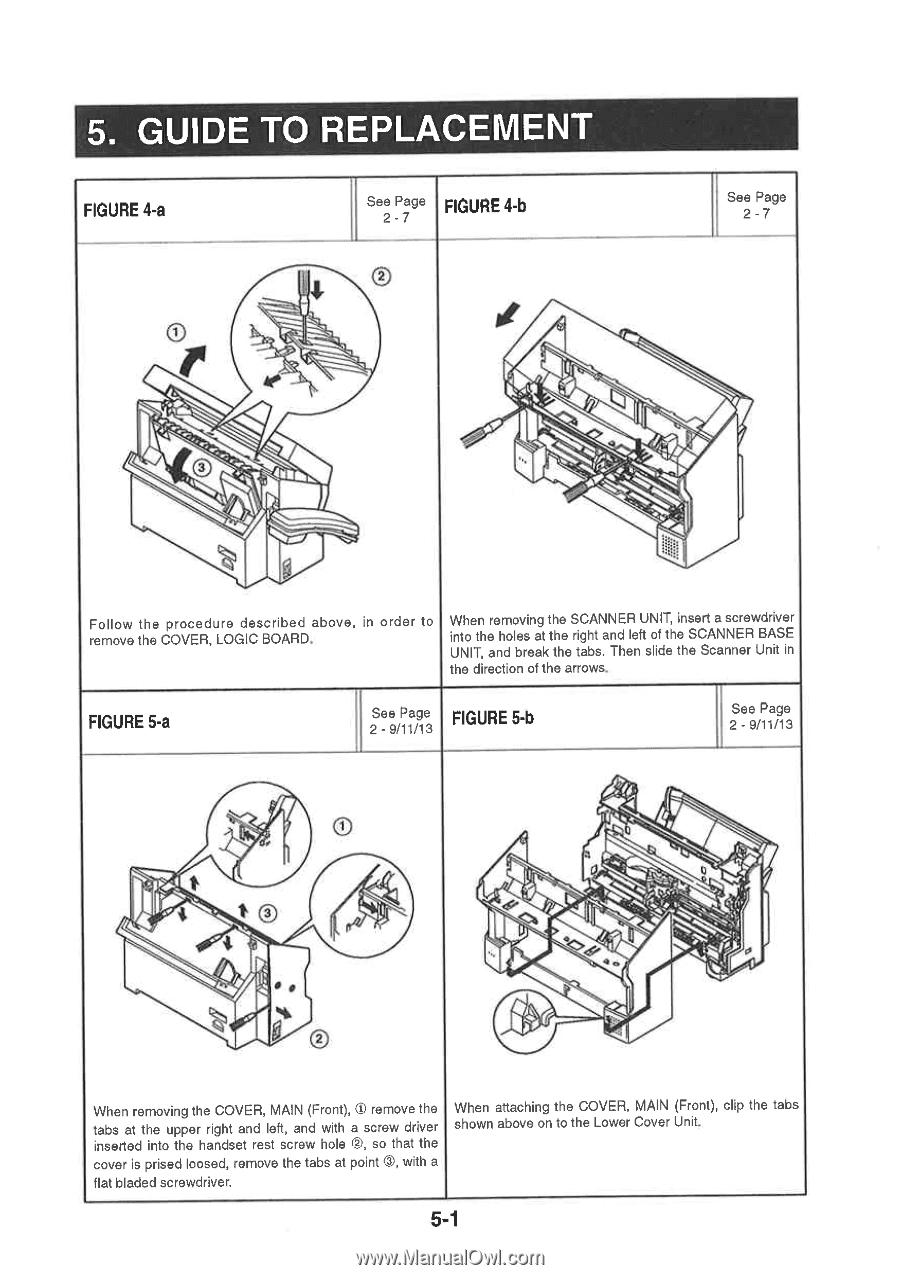
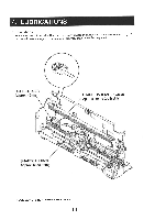
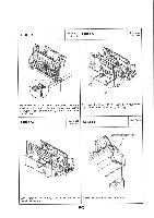
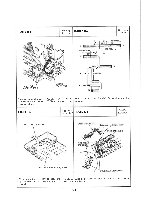
5. GUIDE TO REPLACEMENT FIGURE 4-a See Page FIGURE 4-b 2 - 7 See Page 2 -7 O Follow the procedure described above, in order to remove the COVER, LOGIC BOARD, When removing the SCANNER UNIT, insert a screwdriver into the holes at the right and left of the SCANNER BASE UNIT, and break the tabs. Then slide the Scanner Unit in the direction of the arrows. FIGURE 5-a See Page 2 - 9/11/13 FIGURE 5-b See Page 2 - 9/11/13 4 4 445. '4 /4 *4'•44 - t When removing the COVER, MAIN (Front), 0 remove the tabs at the upper right and left, and with a screw driver inserted into the handset rest screw hole ®, so that the cover is prised loosed, remove the tabs at point 0, with a flat bladed screwdriver. When attaching the COVER, MAIN (Front), clip the tabs shown above on to the Lower Cover Unit 5-1
-
 1
1 -
2
-
3
-
4
-
5
-
6
-
7
-
8
-
9
-
10
-
11
-
12
-
13
-
14
-
15
-
16
-
17
-
18
-
19
-
20
-
21
-
22
-
23
-
24
-
25
-
26
-
27
-
28
-
29
-
30
-
31
-
32
-
33
-
34
-
35
-
36
-
37
-
38
-
39
-
40
-
41
-
42
-
43
-
44
-
45
-
46
-
47
-
48
-
49
-
50
-
51
-
52
-
53
-
54
-
55
-
56
-
57
-
58
-
59
-
60
-
61
-
62
-
63
-
64
-
65
-
66
-
67
-
68
-
69
-
70
-
71
-
72
-
73
-
74
-
75
-
76
-
77
-
78
-
79
-
80
-
81
-
82
-
83
-
 84
84 -
 85
85 -
 86
86 -
 87
87 -
 88
88 -
 89
89 -
 90
90 -
 91
91 -
 92
92 -
 93
93 -
 94
94 -
95
-
96
-
97
-
98
-
99
-
100
-
101
-
102
-
103
 |
 |