Canon MultiPASS 800 Parts Catalog - Page 91
Canon MultiPASS 800 Manual
 |
View all Canon MultiPASS 800 manuals
Add to My Manuals
Save this manual to your list of manuals |
Page 91 highlights
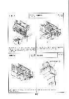
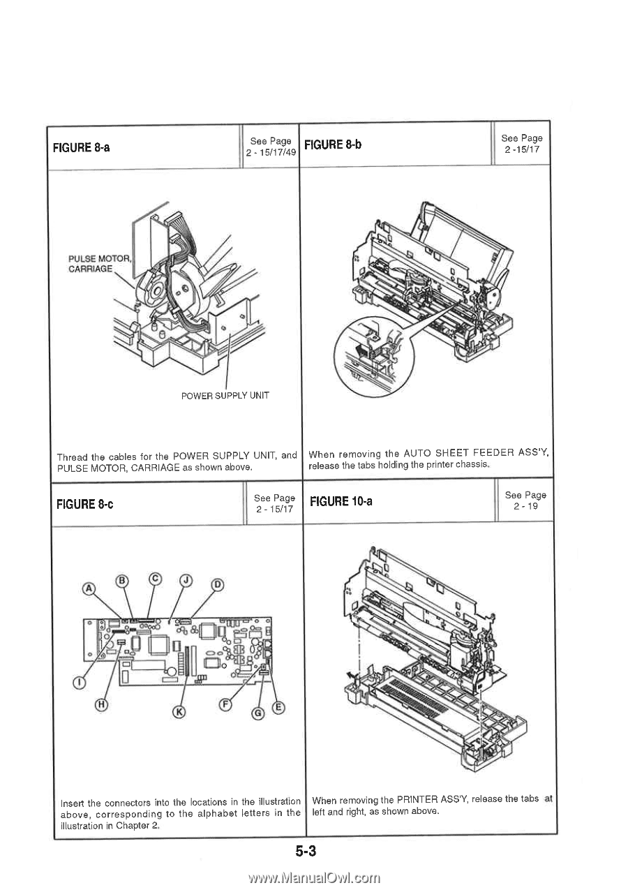
FIGURE 8-a See Page 2 - 15/17/49 FIGURE 8-b See Page 2 -15/17 PULSE MOTOR. CARRIAGE 014 a POWER SUPPLY UNIT Thread the cables for the POWER SUPPLY UNIT, and When removing the AUTO SHEET FEEDER ASS'Y, PULSE MOTOR, CARRIAGE as shown above. release the tabs holding the printer chassis. FIGURE 8-c See Page 2 - 15/17 FIGURE 10-a See Page 2-19 A B C J U 0 aB 0O H F K G Insert the connectors into the locations in the illustration When removing the PRINTER ASS'Y, release the tabs at above, corresponding to the alphabet letters in the left and right, as shown above. illustration in Chapter 2. 5-3
-
 1
1 -
2
-
3
-
4
-
5
-
6
-
7
-
8
-
9
-
10
-
11
-
12
-
13
-
14
-
15
-
16
-
17
-
18
-
19
-
20
-
21
-
22
-
23
-
24
-
25
-
26
-
27
-
28
-
29
-
30
-
31
-
32
-
33
-
34
-
35
-
36
-
37
-
38
-
39
-
40
-
41
-
42
-
43
-
44
-
45
-
46
-
47
-
48
-
49
-
50
-
51
-
52
-
53
-
54
-
55
-
56
-
57
-
58
-
59
-
60
-
61
-
62
-
63
-
64
-
65
-
66
-
67
-
68
-
69
-
70
-
71
-
72
-
73
-
74
-
75
-
76
-
77
-
78
-
79
-
80
-
81
-
82
-
83
-
84
-
85
-
 86
86 -
 87
87 -
 88
88 -
 89
89 -
 90
90 -
 91
91 -
 92
92 -
 93
93 -
 94
94 -
 95
95 -
 96
96 -
97
-
98
-
99
-
100
-
101
-
102
-
103
 |
 |
FIGURE
8-a
See
Page
2
-
15/17/49
FIGURE
8-b
PULSE
MOTOR.
CARRIAGE
a
0
14
POWER
SUPPLY
UNIT
Thread
the
cables
for
the
POWER
SUPPLY
UNIT,
and
PULSE
MOTOR,
CARRIAGE
as
shown
above.
See
Page
2
-15/17
When
removing
the
AUTO
SHEET
FEEDER
ASS'Y,
release
the
tabs
holding
the
printer
chassis.
FIGURE
8-c
See
Page
2
-
15/17
FIGURE
10-a
B
A
0
C
H
J
U
aB
0O
K
F
G
Insert
the
connectors
into
the
locations
in
the
illustration
above,
corresponding
to
the
alphabet
letters
in
the
illustration
in
Chapter
2.
See
Page
2-19
When
removing
the
PRINTER
ASS'Y,
release
the
tabs
at
left
and
right,
as
shown
above.
5-3