Canon PC940 Service Manual - Page 223
Power Supply, Outline,
 |
View all Canon PC940 manuals
Add to My Manuals
Save this manual to your list of manuals |
Page 223 highlights
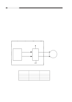
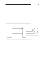
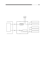
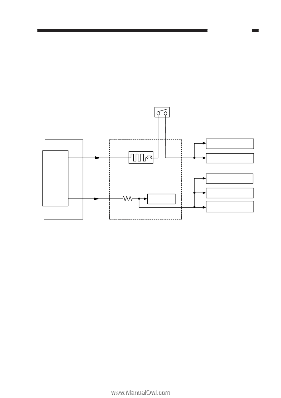
CHAPTER 8 ADF J. Power Supply 1. Outline Figure 8-124 shows the routes of power supply. The ADF is supplied by the copier with 5 V and 24 V. The 24V supply is cut off when the ADF is opened, i.e., when the ADF switch (MS1) turns off. The 5V supply will continue to keep each sensor powered even when the ADF is opened. ADF switch (MS1) J6-1 COM J6-2 NO J101-1 24V J1-1 Composite power supply PCB J101-3 5V J1-3 Circuitbreaker (CB1) Fuse resistor (R1) Logic Copier ADF controller PCB Figure 8-124 Belt motor (M1) Pickup motor (M2) Delivery sensor (PI1) Registration sensor (PI2) Original placement sensor (PI3) COPYRIGHT © 1999 CANON INC. CANON PC800s/900s REV.0 AUG. 1999 PRINTED IN JAPAN (IMPRIME AU JAPON) 8-17
-
 1
1 -
2
-
3
-
4
-
5
-
6
-
7
-
8
-
9
-
10
-
11
-
12
-
13
-
14
-
15
-
16
-
17
-
18
-
19
-
20
-
21
-
22
-
23
-
24
-
25
-
26
-
27
-
28
-
29
-
30
-
31
-
32
-
33
-
34
-
35
-
36
-
37
-
38
-
39
-
40
-
41
-
42
-
43
-
44
-
45
-
46
-
47
-
48
-
49
-
50
-
51
-
52
-
53
-
54
-
55
-
56
-
57
-
58
-
59
-
60
-
61
-
62
-
63
-
64
-
65
-
66
-
67
-
68
-
69
-
70
-
71
-
72
-
73
-
74
-
75
-
76
-
77
-
78
-
79
-
80
-
81
-
82
-
83
-
84
-
85
-
86
-
87
-
88
-
89
-
90
-
91
-
92
-
93
-
94
-
95
-
96
-
97
-
98
-
99
-
100
-
101
-
102
-
103
-
104
-
105
-
106
-
107
-
108
-
109
-
110
-
111
-
112
-
113
-
114
-
115
-
116
-
117
-
118
-
119
-
120
-
121
-
122
-
123
-
124
-
125
-
126
-
127
-
128
-
129
-
130
-
131
-
132
-
133
-
134
-
135
-
136
-
137
-
138
-
139
-
140
-
141
-
142
-
143
-
144
-
145
-
146
-
147
-
148
-
149
-
150
-
151
-
152
-
153
-
154
-
155
-
156
-
157
-
158
-
159
-
160
-
161
-
162
-
163
-
164
-
165
-
166
-
167
-
168
-
169
-
170
-
171
-
172
-
173
-
174
-
175
-
176
-
177
-
178
-
179
-
180
-
181
-
182
-
183
-
184
-
185
-
186
-
187
-
188
-
189
-
190
-
191
-
192
-
193
-
194
-
195
-
196
-
197
-
198
-
199
-
200
-
201
-
202
-
203
-
204
-
205
-
206
-
207
-
208
-
209
-
210
-
211
-
212
-
213
-
214
-
215
-
216
-
217
-
 218
218 -
 219
219 -
 220
220 -
 221
221 -
 222
222 -
 223
223 -
 224
224 -
 225
225 -
 226
226 -
 227
227 -
 228
228 -
229
-
230
-
231
-
232
-
233
-
234
-
235
-
236
-
237
-
238
-
239
-
240
-
241
-
242
-
243
-
244
-
245
-
246
-
247
-
248
-
249
-
250
-
251
-
252
-
253
-
254
-
255
-
256
-
257
-
258
-
259
-
260
-
261
-
262
-
263
-
264
-
265
-
266
-
267
-
268
-
269
-
270
-
271
-
272
-
273
-
274
-
275
-
276
-
277
-
278
-
279
-
280
-
281
-
282
-
283
-
284
-
285
-
286
-
287
-
288
-
289
-
290
-
291
-
292
-
293
-
294
-
295
-
296
-
297
-
298
-
299
-
300
-
301
-
302
-
303
-
304
-
305
-
306
-
307
-
308
-
309
-
310
-
311
-
312
-
313
-
314
-
315
-
316
-
317
-
318
-
319
-
320
-
321
-
322
-
323
-
324
-
325
-
326
-
327
-
328
-
329
-
330
-
331
-
332
-
333
-
334
-
335
-
336
-
337
-
338
-
339
-
340
-
341
-
342
-
343
-
344
-
345
-
346
-
347
-
348
-
349
-
350
-
351
-
352
-
353
-
354
-
355
-
356
-
357
-
358
-
359
-
360
-
361
-
362
-
363
-
364
-
365
-
366
-
367
-
368
-
369
-
370
-
371
-
372
-
373
-
374
-
375
-
376
-
377
-
378
-
379
-
380
-
381
-
382
-
383
-
384
-
385
-
386
-
387
-
388
-
389
-
390
-
391
-
392
-
393
 |
 |
CHAPTER 8
ADF
COPYRIGHT
©
1999
CANON INC.
CANON
PC800s/900s REV.0 AUG. 1999 PRINTED IN JAPAN (IMPRIME AU JAPON)
8-17
J.
Power Supply
1.
Outline
Figure 8-124 shows the routes of power supply.
The ADF is supplied by the copier with 5 V and 24 V. The 24V supply is cut off when the ADF
is opened, i.e., when the ADF switch (MS1) turns off. The 5V supply will continue to keep each
sensor powered even when the ADF is opened.
Figure 8-124
Logic
Circuitbreaker
(CB1)
Copier
ADF controller PCB
Fuse resistor
(R1)
24V
5V
J1-3
J1-1
J6-2
J6-1
COM
NO
Delivery sensor (PI1)
Belt motor (M1)
Pickup motor (M2)
ADF switch
(MS1)
Composite
power
supply
PCB
J101-1
J101-3
Registration sensor (PI2)
Original placement sensor (PI3)