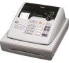
Casio PCRT275 Owners Manual
Casio PCRT275 - Cash Register w/ 15 Depts Manual
 |
View all Casio PCRT275 manuals
Add to My Manuals
Save this manual to your list of manuals |
Casio PCRT275 manual content summary:
- Casio PCRT275 | Owners Manual - Page 1
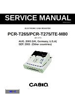
SERVICE MANUAL (without price) ELECTRONIC CASH REGISTER PCR-T265/PCR-T275/TE-M80 (EX-270) AUG. 2003 (UK, Germany, U.S.A) SEP. 2003 (Other countries) INDEX - Casio PCRT275 | Owners Manual - Page 2
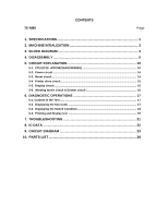
5-6. Winding motor circuit & Drawer circuit 16 6. DIAGNOSTIC OPERATIONS 17 6-1. Content of the Test ...17 6-2. Displaying the Key Code 17 6-3. Displaying the Switch Condition 18 6-4. Printing and Display test 19 7. TROUBLESHOOTING 21 8. IC DATA ...22 9. CIRCUIT DIAGRAM 23 10. PARTS LIST 28 - Casio PCRT275 | Owners Manual - Page 3
Number of control bit Mask ROM (Built-in) RAM (Built-in) Name Print method Head specification Paper cut Paper supply method Life Type Size Roll diam Thickness UK: µPD784215AGC2368EU U.S.A./CANADA: µPD784215AGC2378EU Other countries: µPD784215AGC2388EU 16 bit 128 Kbytes 5120 bytes LTPZ225B-C192 - Casio PCRT275 | Owners Manual - Page 4
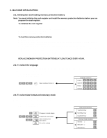
Europe, Other countries UK/Canada 1-5. Option List DEVICE NAME • Wet cover • Roll paper • Roll paper • Cash Tray • Cash Tray • Cash Tray • Cash Tray • Cash Tray • Tray Lid MODEL of used batteries according to the manufacture's instructions. VORSICHT ! Explosionsgefahr bei unsachgemäßem Austausch - Casio PCRT275 | Owners Manual - Page 5
To select the language You can select the default printing language depending on the requirements in your area. Example: Change the language to Spanish. 1. Set the mode switch to PGM. 2. Press the following keys. 2999 HELP Select numbers from list A. Language selections English 1 9 9 9 Spanish - Casio PCRT275 | Owners Manual - Page 6
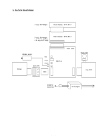
3. BLOCK DIAGRAM 7 seg LED*8digits Rear display : E270-E2-2 7 seg LED*8digits +14 seg LED*1digit Main display : E270-E2-1 Winder motor Printer E271-PR Batt Power Drower FFC E270-1 Mode SW Key FPC POWER DC6V/2A AC Adapter - 4 - - Casio PCRT275 | Owners Manual - Page 7
4. DISASSEMBLY s Removing the register 1. Remove the journal cover and then the WINDING PULLY. 2. Remove the battery cover and then the battery. 3. Remove the two screws. 4. Separate the main unit as shown below. Screws - 5 - - Casio PCRT275 | Owners Manual - Page 8
5. Remove the connector (CN7) as well as the power jack, and then separate the main unit from the drawer. s Removing the main PCB 6. Remove the connectors (CN6, CN8), FPCs(CN1, CN3, CN9) and the two screws and then remove the main PCB. CN1 CN6 CN3 CN8 Screws CN9 s Disassembling the keyboard - Casio PCRT275 | Owners Manual - Page 9
s Removing the switch PCB (E270-PR) 9. Remove the two screws. Lift up the PCB and remove the FPC and then the PCB. s Disassembling the display unit 10. Remove the display cover. Hooks 3 Hooks 1 Hooks 4 Hooks 2 (1) Open the printer cover and remove Hook1 and Hook2. (2) Remove Hook3 and Hook4. - Casio PCRT275 | Owners Manual - Page 10
12. Remove the LCD board. Hooks Hooks s Removing the key unit 13. Removing one screw and then the key unit. Screw s Removing the printer unit 14. Remove the three screws and then the printer unit. Screws - 8 - - Casio PCRT275 | Owners Manual - Page 11
s Disassembling the drawer (DL-1329/DL-1841) 15. Remove one screw and then the power unit. Screw 16. Pull the lever and remove the tray. 17. Remove the three screws and then the top plate. 18. Remove the three screws and the solenoid. Screws - 9 - Hooks - Casio PCRT275 | Owners Manual - Page 12
/RD P63/A19 P120/RTP0 P121/RTP1 P122/RTP2 P123/RTP3 P124/RTP4 P125/RTP5 P126/RTP6 P127/RTP7 VDD X2 X1 VSS XT2 XT1 RESET P00/INTP0 P01/INTP1 P02/INTP2/NMI P03/INTP3 P04/INTP4 P05/INTP5 P06/INTP6 AVDD AVREF0 P10/ANI0 100 99 98 97 96 95 - Casio PCRT275 | Owners Manual - Page 13
CLOCK OUTPUT CONTROL BUZZER OUTPUT 78K/IV CPU CORE ROM RAM UART/IOE1 BAUD-RATE GENERATOR UART/IOE2 BAUD-RATE GENERATOR CLOCKED SERIAL INTERFACE BUS I/F PORT0 PORT1 PORT2 PORT3 PORT4 PORT5 PORT6 PORT7 P70-P72 P80-P87 P90-P95 P100-P103 P120-P127 P130,P131 RESET X1 X2 XT1 XT2 VDD VSS - 11 - - Casio PCRT275 | Owners Manual - Page 14
49 P81/A1 50 P82/A2 I/O DESCRIPTION IO 8 bit input/output PORT - Power Supply - I Main system Clock - GND - I Sub system Clock I Reset IO 7 bit input/output PORT - A/D CONVERTER POWER SUPPLY - Application of Standard Voltage for A/D CONVERTER I 8 bit input PORT A/D CONVERTER - Casio PCRT275 | Owners Manual - Page 15
100 P95 I/O DESCRIPTION IO 8 bit input/output PORT IO 8 bit input/output PORT IO 8 bit input/output PORT - GND IO 8 bit input/output PORT - Power Supply IO 4 bit input/output PORT IO 8 bit input/output PORT - TEST pin IO 6 bit input/output PORT - 13 - - Casio PCRT275 | Owners Manual - Page 16
16V220uF C32 16V1000uF R80 270 1/4W 5-2. Power circuit To power supply unit CN11 HEC3600-010510 VACP 1 GND 2 3 VACP GND CN10 P126/RTP6 9 P127/RTP7 10 VDD X2 11 12 X1 13 VSS 14 XT2 XT1 15 RESET 16 17 P00/INTP0 18 P01/INTP1 P02/INTP2/NMI 19 P03/INTP3 20 21 P04/INTP4 - Casio PCRT275 | Owners Manual - Page 17
P122/RTP2 4 5 P123/RTP3 6 P124/RTP4 7 P125/RTP5 P126/RTP6 8 P127/RTP7 9 10 VDD 11 X2 X1 12 VSS 13 14 XT2 15 XT1 16 RESET P00/INTP0 17 18 P01/INTP1 19 P02/INTP2/NMI 20 P03/INTP3 P04/INTP4 21 22 P05/INTP5 23 P06/INTP6 24 AVDD AVREF0 - Casio PCRT275 | Owners Manual - Page 18
P122/RTP2 4 P123/RTP3 5 6 P124/RTP4 7 P125/RTP5 P126/RTP6 8 P127/RTP7 9 10 VDD 11 X2 12 X1 VSS 13 14 XT2 15 XT1 16 RESET P00/INTP0 17 18 P01/INTP1 19 P02/INTP2/NMI 20 P03/INTP3 P04/INTP4 21 22 P05/INTP5 23 P06/INTP6 24 AVDD AVREF0 - Casio PCRT275 | Owners Manual - Page 19
Displaying the Switch Condition Press the clear key, or change the status of switches. 3 Printing and Display test One digit number + #2 (SUB TOTAL) key 6-2. Displaying the Key Code Press any key other than the ten keys and clear key to dipslay the hard key code as shown below. (Display) 019 32 - Casio PCRT275 | Owners Manual - Page 20
clear key, or change the status of switches to display the current conditions. [DISPLAY] Mode SW 1:PGM, 2:RF, 3:REG, 4:CAL, 5:X, 6:Z, 8:OFF, 0:no contact FEED key 1:ON, 0:OFF No display PAD2 1:SHORT 0:OPEN PAD1 1:SHORT 0:OPEN Printer status No display 1:OPEN or no paper 0:CLOSE, with paper 0:Fixed - Casio PCRT275 | Owners Manual - Page 21
input (the test proceeds by the input of any key other than the clear key, ten keys and FEED key.) • Time and date setting Set the time and date at 23:59 on 31 December, 1994. • Drawer open • Test print • Receipt issuing (only in the receipt mode) • Test display (display) : 12345678 Switching the - Casio PCRT275 | Owners Manual - Page 22
is displayed until a power down occurs. display (display) BBB BBB: battery voltage Print test Operation : 8 #2 SUB TOTAL All the fonts are printed. Time display test Operation : 9 #2 SUB TOTAL Time is displayed until the clear key is pressed or a power down occurs. Ending the test mode To leave - Casio PCRT275 | Owners Manual - Page 23
7. TROUBLESHOOTING Symptom/Problem Most common causes Solutions 1 E01 appears on the display. Changing modes without com- Return key to where it stops pleting transaction. buzzing and press . CA/AMT /TEND 2 When the printer does not print properly. Check the platen arm/shut down and close - Casio PCRT275 | Owners Manual - Page 24
8. IC DATA 1. ULN2003AFW (IC1, IC2) I1 1 I2 2 I3 3 I4 4 I5 5 I6 6 I7 7 GND 10 20 O1 19 O2 18 O3 17 O4 16 O5 15 O6 14 O7 11 COMMON 2. S-80819CNNB-B8E (IC6), S-80850CNNB-B9B (IC7) 4 3 1 2 No. Symbol Description 1 OUT Voltage detection output pin 2 VDD Voltage input pin 3 NC*1 Non- - Casio PCRT275 | Owners Manual - Page 25
9. CIRCUIT DIAGRAM MODEL : TE-M80 (EX-270) CONTENTS 1. MAIN PCB CIRCUIT ...24 2. E270-E2-1 CIRCUIT ...25 3. E270-E2-1 CIRCUIT ...26 4. E270-PRINTER CIRCUIT ...27 - 23 - - Casio PCRT275 | Owners Manual - Page 26
R84 R85 ??? C34 15pF X1 C33 12pF VDD 0.1uF C35 C-002AX ??? C4 ??? C5 C36 ??? IC3 1 28 2 RESET CE 27 3 TST1 SCLK 26 R15 ??? TST2 4 SIN/SO 25 5 XT0 SOUT 24 R14 ??? 6 XT1 (CNG) Q4 2SB1126 Model TE-M80 CASIO COMPUTER CO.,LTD. (EX-270) Board No. Name E270-1 MAIN BOARD Drawing No - Casio PCRT275 | Owners Manual - Page 27
J2 J1 Model TE-M80 CASIO COMPUTER CO.,LTD. (EX-270) Board No. Name E270-E2-1 E270-E2-1 CIRCUIT - 25 - Drawing No. - Casio PCRT275 | Owners Manual - Page 28
J1 J2 Model TE-M80 CASIO COMPUTER CO.,LTD. (EX-270) Board No. Name E270-E2-2 E270-E2-2 CIRCUIT - 26 - Drawing No. - Casio PCRT275 | Owners Manual - Page 29
Model TE-M80 CASIO COMPUTER CO.,LTD. (EX-270) Board No. E270-PR Name E270-PRINTER CIRCUIT Drawing No. - 27 - - Casio PCRT275 | Owners Manual - Page 30
10. PARTS LIST MODEL : TE-M80/PCR-T265/PCR-T275 (EX-270) Explode view ...29 TE-M80 1. MAIN PCB BLOCK ...31 2. MAIN DISPLAY & CUSTOMER DISPLAY BLOCK 31 3. BUTTON BLOCK ...31 4. POWER SUPPLY BLOCK ...32 5. UPPER CASE BLOCK ...32 6. PRINTER PCB BLOCK...33 PCR-T265/PCR-T275 1. MAIN PCB BLOCK ...34 2. - Casio PCRT275 | Owners Manual - Page 31
UPPER CASE (TE-M80/PCR-T265/PCR-T275) 63 59 61 62 32 60 42 49 48 36 41 50 47 33 38 58 53 51 34 2 31 57 46 45 40 52 43 35 44 65 55 64 67 37 56 54 1 34 Power supply block 30 66 - 29 - 29 With Power Cord - Casio PCRT275 | Owners Manual - Page 32
KEYBOARD (TE-M80/PCR-T265/PCR-T275) 20 5 21 6 to 17 24 27 19 18 26 23 22 25 21 20 6 to 17 18 19 18 22 28 23 22 22 - 30 - - Casio PCRT275 | Owners Manual - Page 33
PARTS PRICE LIST TE-M80 N Item Code No. Parts Name 1. MAIN PCB BLOCK N 1 10131708 PCB ASSY/E270-1 N 1 10140512 PCB ASSY/E270-1 N 1 10140513 PCB ASSY/E270-1 N IC4 10137724 LSI N IC4 10136098 LSI N IC6 10136173 IC/RESET /CHIP N IC7 10095125 IC/RESET 2. MAIN DISPLAY & CUSTOMER - Casio PCRT275 | Owners Manual - Page 34
SUPPLY ASSY POWER SUPPLY ASSY POWER SUPPLY ASSY CORD/POWER CORD/POWER CORD/POWER CORD/POWER MOUNT/POWER CORD E270 HOLDER/PS E270 SCREW TIE/INSULOCK CASE/UPPER E270 COVER/PRINTER E270 BUTTON /EJECT ARM-EJECT MOUNT/PRINTER E270 SHAFT/E270 MOUNT/PCB E270 SPRING/PRESS E270 PLATE/SW E270 MODE KEY Price - Casio PCRT275 | Owners Manual - Page 35
N Item Code No. Parts Name Specification N 55 N 56 57 N E270 SPOOL/PAPER HOLDER E270 PANEL/DISPLAY E270 KEY SET SUB ASSY KEY SET SUB HLMP-1503 ERD-25TJ331V SKHHAL 52807-3010 52806-2410 LH-5-10.5 Q'ty Other Countries Price R Europe UK Germany Australia Plug Type Code UK USA 1 1 1 1 - Casio PCRT275 | Owners Manual - Page 36
PCR-T265/PCR-T275 N Item Code No. Parts Name 1. MAIN PCB BLOCK N 1 10131709 PCB ASSY/E270-1 N IC4 10139759 LSI N IC6 10136173 IC/RESET GRM21BB11H104KA11L MCH185A101J MCH182FN104Z MCH182CN102K MNR14E0ABJ103 MCR03EZPFX2002 MCR03EZHJ103 Q'ty Canada U.S.A. Price R Code OSS WHC 1 1 1 CP - Casio PCRT275 | Owners Manual - Page 37
PCR-T265/PCR-T275 N Item Code No. Parts Name Specification N CN1 N N N R1-7,10-20(Main) R1-15 PLATE/L 7E270 POWER SUPPLY ASSY CORD/POWER MOUNT RJE500716-001V03 RJE500718-001V01 RJE500719-001V02 RJE500724-001V01 RJE500725-001V01 Q'ty Canada U.S.A. Price R Code OSS WHC 1 1 1 AC C 1 1 1 - Casio PCRT275 | Owners Manual - Page 38
PCR-T265/PCR-T275 N Item Code No. Parts Name SPOOL/PAPER HOLDER E270 PANEL/DISPLAY E270 PANEL/DISPLAY E270 KEY SET -001V01 RJE500764*001V01 HLMP-1503 ERD-25TJ331V SKHHAL 52807-3010 52806-2410 LH-5-10.5 Q'ty Canada U.S.A. Price R Code OSS WHC 2 2 2 AA C 1 1 1 AA C 1 1 1 AF C 1 1 1 - Casio PCRT275 | Owners Manual - Page 39
7. DRAWER (DL-1329) 21 2 5 9 4 6 7 22 19 14 18 12 11 8 1 13 16 3 17 15 20 10 - 37 - - Casio PCRT275 | Owners Manual - Page 40
DL-1329(S type) U.S.A. N Item Code No. Parts Name Specification N 1 10127601 CASE/MAIN RJE500670-001V01 N 2 10127602 /DL-1329 E341256-40 Qt'y 1 1 2 1 1 1 1 5 1 1 2 2 4 2 1 1 3 4 4 1 4 2 2 1 1 1 4 1 3 1 3 1 Price code BC BG AP AA AA AA AA AD AW AZ AA AD AA AD AP AA AA AG AK AS BJ Rank - Casio PCRT275 | Owners Manual - Page 41
8. DRAWER (DL-1841) 21 2 5 9 4 6 7 22 19 14 18 12 11 8 1 13 16 3 17 15 20 10 - 39 - - Casio PCRT275 | Owners Manual - Page 42
type) Germany, Europe, Other countries N Item Code No. Parts Name Specification N 1 10127601 CASE/MAIN RJE500670-001V01 N 2 E341256-41 Qt'y 1 1 2 1 1 1 1 5 1 1 2 2 4 2 1 1 2 3 3 1 3 2 2 1 1 1 4 1 3 1 3 1 Price code BC BG AP AA AA AA AA AD AW AZ AA AD AA AD AP AA AA AG AK AS BJ Rank - Casio PCRT275 | Owners Manual - Page 43
9. DRAWER (DL-2794) 20 19 18 16 17 15 30 29 10 34 32 12 33 13 31 3 13 11 2 14 13 28 5 9 22 4 23 27 6 7 1 8 22 27 24 21 26 25 - 41 - - Casio PCRT275 | Owners Manual - Page 44
Europe, Other countries N Item Code No. Parts Name 1. MAIN CASE BLOCK 1 10078897 2 55000619 E140497-1 3X10 NI 6X13X1.0 ZMC-3 E140505-1 E140058-1 E340173A-1 ZD43652 E341290*1 E441357-1 E240845-1 3X8 ZMC-3 3X5 NI Qt'y Price Rank code 1 BS X 2 AG B 2 AA X 1 AA C 1 AA C 4 X 1 AA X 1 - Casio PCRT275 | Owners Manual - Page 45
10. DRAWER (DL-2796) 20 19 18 16 17 15 10 32 30 12 31 13 29 3 13 11 2 14 13 28 5 9 22 4 23 27 6 7 1 8 22 27 24 21 26 25 - 43 - - Casio PCRT275 | Owners Manual - Page 46
DL-2796(M type) UK, Canada N Item Code No. Parts Name Specification 1. MAIN CASE BLOCK 5X30 E412092-1 CL-16 E140497-1 3X10 NI 6X13X1.0 ZMC-3 ZD43751 ZD43652 E341290*1 E441357-1 E240845-1 3X8 ZMC-3 3X5 NI Qt'y Price Rank code 1 BS X 2 AG B 2 AA X 1 AA C 1 AA C 4 X 1 AA X 1 AA - Casio PCRT275 | Owners Manual - Page 47
CASIO TECHNO CO.,LTD. Overseas Service Division 6-2, Hon-machi 1-Chome Shibuya-ku, Tokyo 151-8543, Japan
-
 1
1 -
 2
2 -
 3
3 -
 4
4 -
 5
5 -
 6
6 -
 7
7 -
8
-
9
-
10
-
11
-
12
-
13
-
14
-
15
-
16
-
17
-
18
-
19
-
20
-
21
-
22
-
23
-
24
-
25
-
26
-
27
-
28
-
29
-
30
-
31
-
32
-
33
-
34
-
35
-
36
-
37
-
38
-
39
-
40
-
41
-
42
-
43
-
44
-
45
-
46
-
47
 |
 |
SERVICE MANUAL
ELECTRONIC CASH REGISTER
(without price)
PCR-T265/PCR-T275/TE-M80
(EX-270)
AUG. 2003 (UK, Germany, U.S.A)
SEP. 2003
(Other countries)