Cisco 3750-48TS-S Hardware Installation Guide - Page 133
Crossover Cable and Adapter Pinouts, Identifying a Crossover Cable
 |
UPC - 746320805184
View all Cisco 3750-48TS-S manuals
Add to My Manuals
Save this manual to your list of manuals |
Page 133 highlights
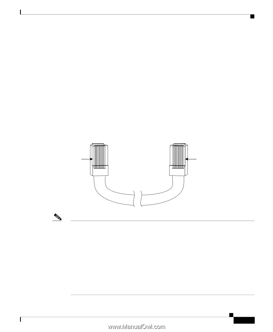
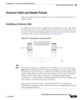
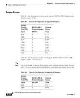
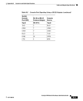
Appendix B Connector and Cable Specifications Cable and Adapter Specifications Crossover Cable and Adapter Pinouts This section describes how to identify a crossover cable and also describes the adapter pinouts. Identifying a Crossover Cable To identify a crossover cable, compare the two modular ends of the cable. Hold the cable ends side-by-side, with the tab at the back. The wire connected to the pin on the outside of the left plug should be the same color as the wire connected to the pin on the outside of the right plug. (See Figure B-11.) Figure B-11 Identifying a Crossover Cable Pin 1 on one connector and pin 8 on the other connector should be the same color. Pin 1 Pin 8 H10632 Note On switches running Cisco IOS Release 12.1(14)EA1 or later, you can use the mdix auto command in the CLI to enable the automatic crossover feature. When the automatic crossover feature is enabled, the switch detects the required cable type for copper Ethernet connections and configures the interfaces accordingly. Therefore, you can use either a crossover or a straight-through cable for connections to a copper 10/100 or 10/100/1000 port on the switch, regardless the type of device on the other end of the connection. The automatic crossover feature is disabled by default. For configuration information for this feature, refer to the switch software configuration guide or the switch command reference. 78-15136-02 Catalyst 3750 Switch Hardware Installation Guide B-9
-
 1
1 -
2
-
3
-
4
-
5
-
6
-
7
-
8
-
9
-
10
-
11
-
12
-
13
-
14
-
15
-
16
-
17
-
18
-
19
-
20
-
21
-
22
-
23
-
24
-
25
-
26
-
27
-
28
-
29
-
30
-
31
-
32
-
33
-
34
-
35
-
36
-
37
-
38
-
39
-
40
-
41
-
42
-
43
-
44
-
45
-
46
-
47
-
48
-
49
-
50
-
51
-
52
-
53
-
54
-
55
-
56
-
57
-
58
-
59
-
60
-
61
-
62
-
63
-
64
-
65
-
66
-
67
-
68
-
69
-
70
-
71
-
72
-
73
-
74
-
75
-
76
-
77
-
78
-
79
-
80
-
81
-
82
-
83
-
84
-
85
-
86
-
87
-
88
-
89
-
90
-
91
-
92
-
93
-
94
-
95
-
96
-
97
-
98
-
99
-
100
-
101
-
102
-
103
-
104
-
105
-
106
-
107
-
108
-
109
-
110
-
111
-
112
-
113
-
114
-
115
-
116
-
117
-
118
-
119
-
120
-
121
-
122
-
123
-
124
-
125
-
126
-
127
-
 128
128 -
 129
129 -
 130
130 -
 131
131 -
 132
132 -
 133
133 -
 134
134 -
 135
135 -
 136
136 -
 137
137 -
 138
138 -
139
-
140
-
141
-
142
-
143
-
144
-
145
-
146
-
147
-
148
-
149
-
150
-
151
-
152
-
153
-
154
-
155
-
156
-
157
-
158
-
159
-
160
-
161
-
162
-
163
-
164
-
165
-
166
-
167
-
168
-
169
-
170
-
171
-
172
-
173
-
174
-
175
-
176
-
177
-
178
-
179
-
180
-
181
-
182
-
183
-
184
-
185
-
186
-
187
-
188
-
189
-
190
-
191
-
192
-
193
-
194
-
195
-
196
-
197
-
198
 |
 |