Cisco 3750-48TS-S Hardware Installation Guide - Page 153
Starting the Terminal Emulation Software, Connecting to a Power Source
 |
UPC - 746320805184
View all Cisco 3750-48TS-S manuals
Add to My Manuals
Save this manual to your list of manuals |
Page 153 highlights
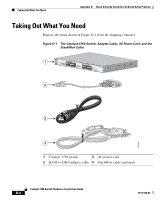
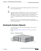
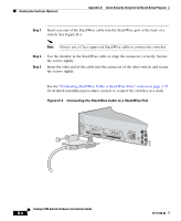
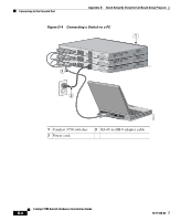
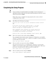
Appendix D Quick Setup By Using the CLI-Based Setup Program Starting the Terminal Emulation Software Starting the Terminal Emulation Software Before you power on the switch, start the terminal emulation session so that you can see the output display from the power-on self-test (POST). The terminal-emulation software-frequently a PC application such as Hyperterminal or ProcommPlus-makes communication between the switch and your PC or terminal possible. Step 1 Step 2 Step 3 Start the terminal-emulation program if you are using a PC or terminal. Start a terminal-emulation session. Configure the baud rate and character format of the PC or terminal to match these console port default characteristics: • 9600 baud • 8 data bits • 1 stop bit • No parity • None (flow control) Connecting to a Power Source Follow these steps to connect to a power source: Step 1 Step 2 Step 3 Connect one end of the supplied AC power cord to the power connector on a switch rear panel. See Figure D-4. Connect the other end of the power cable to a grounded AC outlet. (Optional) If you have a stack, power on all the switches in the stack. Note If you have stacked your switches, refer to the "Powering Considerations" section on page 3-13 for more information. 78-15136-02 Catalyst 3750 Switch Hardware Installation Guide D-9
-
 1
1 -
2
-
3
-
4
-
5
-
6
-
7
-
8
-
9
-
10
-
11
-
12
-
13
-
14
-
15
-
16
-
17
-
18
-
19
-
20
-
21
-
22
-
23
-
24
-
25
-
26
-
27
-
28
-
29
-
30
-
31
-
32
-
33
-
34
-
35
-
36
-
37
-
38
-
39
-
40
-
41
-
42
-
43
-
44
-
45
-
46
-
47
-
48
-
49
-
50
-
51
-
52
-
53
-
54
-
55
-
56
-
57
-
58
-
59
-
60
-
61
-
62
-
63
-
64
-
65
-
66
-
67
-
68
-
69
-
70
-
71
-
72
-
73
-
74
-
75
-
76
-
77
-
78
-
79
-
80
-
81
-
82
-
83
-
84
-
85
-
86
-
87
-
88
-
89
-
90
-
91
-
92
-
93
-
94
-
95
-
96
-
97
-
98
-
99
-
100
-
101
-
102
-
103
-
104
-
105
-
106
-
107
-
108
-
109
-
110
-
111
-
112
-
113
-
114
-
115
-
116
-
117
-
118
-
119
-
120
-
121
-
122
-
123
-
124
-
125
-
126
-
127
-
128
-
129
-
130
-
131
-
132
-
133
-
134
-
135
-
136
-
137
-
138
-
139
-
140
-
141
-
142
-
143
-
144
-
145
-
146
-
147
-
 148
148 -
 149
149 -
 150
150 -
 151
151 -
 152
152 -
 153
153 -
 154
154 -
 155
155 -
 156
156 -
 157
157 -
 158
158 -
159
-
160
-
161
-
162
-
163
-
164
-
165
-
166
-
167
-
168
-
169
-
170
-
171
-
172
-
173
-
174
-
175
-
176
-
177
-
178
-
179
-
180
-
181
-
182
-
183
-
184
-
185
-
186
-
187
-
188
-
189
-
190
-
191
-
192
-
193
-
194
-
195
-
196
-
197
-
198
 |
 |