Cisco AIR-AP1010 Quick Start Guide - Page 15
Pre-Installation Configuration, Configuration Setup - - power
 |
UPC - 882658154027
View all Cisco AIR-AP1010 manuals
Add to My Manuals
Save this manual to your list of manuals |
Page 15 highlights
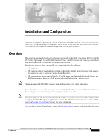
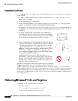
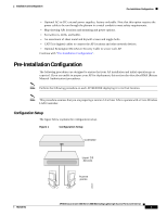
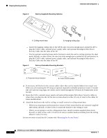
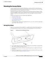
Installation and Configuration Pre-Installation Configuration • Optional AC-to-DC external power supplies, factory-orderable. Note that this option requires the power cable to be run through the plenum in a metal conduit to meet safety requirements. • Map showing APs locations and mounting and power options. • Screwdrivers, drills, and ladder. • An assortment of sheet metal and drywall screws and toggle bolts. • CAT-5 (or higher) cables to connect the AP locations and other network devices. • Optional Kensington MicroSaver Security Cable to secure each AP. Continue with "Pre-Installation Configuration". Pre-Installation Configuration The following procedures are designed to ensure that your AP installation and initial operation go as expected. If you are unable to prepare your AP for deployment, this section also describes RMA (Return Material Authorization) procedures. Note Perform the following procedure on each AP BEFORE deploying it in its final location. Note This procedure assumes that you are preparing a version 3.0 or later APs to operate with a Cisco Wireless LAN Controller. Configuration Setup The figure below explains the configuration setup. Figure 1 onfiguration Setup Configuration Setup Controller Layer 2/3 devices Access points 135670 7817146-01 AP1010 Cisco Aironet 1000 Series IEEE 802.11a/b/g Lightweight Access Points with Internal 3
-
 1
1 -
2
-
3
-
4
-
5
-
6
-
7
-
8
-
9
-
 10
10 -
 11
11 -
 12
12 -
 13
13 -
 14
14 -
 15
15 -
 16
16 -
 17
17 -
 18
18 -
 19
19 -
 20
20 -
21
-
22
-
23
-
24
-
25
-
26
-
27
-
28
-
29
-
30
-
31
-
32
-
33
-
34
-
35
-
36
 |
 |
