Cisco AIR-AP1010 Quick Start Guide - Page 23
Flush Wall Mount
 |
UPC - 882658154027
View all Cisco AIR-AP1010 manuals
Add to My Manuals
Save this manual to your list of manuals |
Page 23 highlights
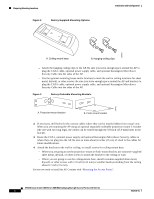
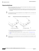
Installation and Configuration Mounting the Access Points Figure 8 Attaching the AP to the Projection-Mount Bracket 135668 5. Attach the cables to the sides of the AP. Note Be sure the cables are routed away from the AP antennas. Note When the AP is powered up and is associated with a Cisco Wireless LAN Controller (Green/Power and Yellow/802.11b/g and/or Yellow or Amber/802.11a LEDs lit), the AP begins broadcasting its beacon signal(s). When this happens, complete the installation as quickly as possible to remove yourself from within 8 inches (20 cm) of the AP to comply with FCC RF radiation exposure guidelines. You have installed the AP. Repeat "Mounting the Access Points" for each AP location, and then continue with "Returning MAC Information". Flush Wall Mount When you are mounting the AP against a wall (flat side toward the inside of the building), use an optional separately orderable flush-mount bracket. 1. Before proceeding, gently screw the two factory-supplied screws and spring washers into the bottom of the AP. Be sure the spring washers have their convex (high center sections) pointing toward the screw heads. Note The AP threaded holes have precision-depth threads. Do not overtighten the screws, or the bracket will not fit under the screw heads. 7817146-01 AP1010 Cisco Aironet 1000 Series IEEE 802.11a/b/g Lightweight Access Points with Internal 11
-
 1
1 -
2
-
3
-
4
-
5
-
6
-
7
-
8
-
9
-
10
-
11
-
12
-
13
-
14
-
15
-
16
-
17
-
 18
18 -
 19
19 -
 20
20 -
 21
21 -
 22
22 -
 23
23 -
 24
24 -
 25
25 -
 26
26 -
 27
27 -
 28
28 -
29
-
30
-
31
-
32
-
33
-
34
-
35
-
36
 |
 |
