Cisco ASR1006-10G-SHA/K9 Installation Guide - Page 27
Connecting DC Input Power to Cisco ASR 1006 Router
 |
View all Cisco ASR1006-10G-SHA/K9 manuals
Add to My Manuals
Save this manual to your list of manuals |
Page 27 highlights
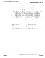
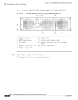
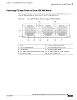
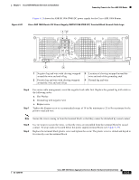
Chapter 6 Cisco ASR 1006 Router Overview and Installation Connecting Power to the Cisco ASR 1006 Router Connecting DC Input Power to Cisco ASR 1006 Router This section describes how to connect the DC power supply into the Cisco ASR 1006 Router. Figure 6-18 shows the ASR1006-PWR-DC power supply of the Cisco ASR 1006 Router. Figure 6-18 Cisco ASR 1006 Router DC Power Supply (ASR1006-PWR-DC) 9 10 55 -48/-60V 40A OFF OUTPUT INPUT INPUT FAIL OK OK ALARMS 60V 1A MAX 8 280023 7 This unit might have more than one power supply connection. All connections must be removed to de-energize the unit. 6 5 4 3 2 1 1 Fans 6 DC power supply ground lugs 2 DB-25 alarm connector 7 DC power supply captive screws 3 Tie-wrap tabs 8 DC power supply handle 4 DC power supply terminal and plastic cover 9 DC power supply On (|) /Off (O) switch 5 Grounding symbol 10 DC power supply LEDs OL-13208-09 Cisco ASR 1000 Series Aggregation Services Routers Hardware Installation Guide 6-27
-
 1
1 -
2
-
3
-
4
-
5
-
6
-
7
-
8
-
9
-
10
-
11
-
12
-
13
-
14
-
15
-
16
-
17
-
18
-
19
-
20
-
21
-
 22
22 -
 23
23 -
 24
24 -
 25
25 -
 26
26 -
 27
27 -
 28
28 -
 29
29 -
 30
30 -
 31
31 -
 32
32 -
33
-
34
-
35
-
36
 |
 |
