Cisco ASR1006-10G-SHA/K9 Installation Guide - Page 30
Cisco ASR 1006 Router DC Power Supply ASR1006-PWR-DC Terminal Block Ground Cable Lugs
 |
View all Cisco ASR1006-10G-SHA/K9 manuals
Add to My Manuals
Save this manual to your list of manuals |
Page 30 highlights
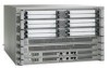
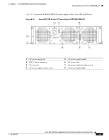
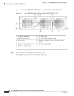
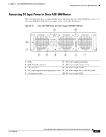
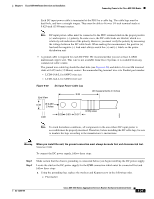
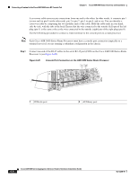
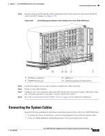
Connecting Power to the Cisco ASR 1006 Router Chapter 6 Cisco ASR 1006 Router Overview and Installation Step 3 Step 4 - Grounding cable lug - Kepnut screw b. Tighten the Kepnut screws on the power supply studs. Attach the other end of the cable to the site's ground connection. Remove the plastic cover from the terminal block. Caution Before you continue to install the terminal block ground wires, stop and perform Step 5. To prevent any contact with metal lead on the ground wire and the plastic cover. Step 5 Wrap the positive and negative lead cables with sleeving. Take each lead wire and cover the area from the lug to the wire with heavy shrink sleeving. Figure 6-21 shows the ASR1006-PWR-DC power supply for the Cisco ASR 1006 Router. Figure 6-21 Cisco ASR 1006 Router DC Power Supply (ASR1006-PWR-DC) Terminal Block Ground Cable Lugs 12 OFF -48/-60V 40A This unit might have more than one power supply connection. All connections must be removed to de-energ 4 3 280024 1 Negative lug and wire with sleeving wrapped 3 Location of sleeving wrapped around the wire around the wire and end of lug and end of the grounding stud 2 Positive lug and wire with sleeving wrapped 4 Ground lug and wire around the wire and end of lug 6-30 Cisco ASR 1000 Series Aggregation Services Routers Hardware Installation Guide OL-13208-09
-
 1
1 -
2
-
3
-
4
-
5
-
6
-
7
-
8
-
9
-
10
-
11
-
12
-
13
-
14
-
15
-
16
-
17
-
18
-
19
-
20
-
21
-
22
-
23
-
24
-
 25
25 -
 26
26 -
 27
27 -
 28
28 -
 29
29 -
 30
30 -
 31
31 -
 32
32 -
 33
33 -
 34
34 -
 35
35 -
36
 |
 |
