Cisco SG102-24 Quick Start Guide - Page 6
Connecting Network Devices - 24 gigabit
 |
View all Cisco SG102-24 manuals
Add to My Manuals
Save this manual to your list of manuals |
Page 6 highlights
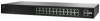
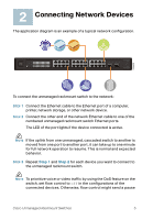
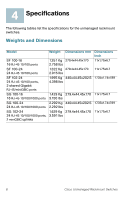
2 Connecting Network Devices The application diagram is an example of a typical network configuration. 193803 SYSTEM Link/Act 1 2 34 56 7 8 9 10 11 12 / miniGBIC1 Gigabit Link/Act 13 14 15 16 17 18 19 20 21 22 23 24 / miniGBIC2 Gigabit 1 2 3 4 13 14 15 16 5 6 7 8 17 18 19 20 9 10 11 12 21 22 23 24 (Shared with 12) (Shared with 24) miniGBIC1 miniGBIC2 Cisco Small Business SR2024 24-P or t 10/ 100/ 1000 Swit ch To connect the unmanaged rackmount switch to the network: STEP 1 Connect the Ethernet cable to the Ethernet port of a computer, printer, network storage, or other network device. STEP 2 Connect the other end of the network Ethernet cable to one of the numbered unmanaged rackmount switch Ethernet ports. The LED of the port lights if the device connected is active. NOTE If the uplink from one unmanaged, cascaded switch to another is moved from one port to another port, it can take up to one minute for full network operation to resume. This is normal and expected behavior. STEP 3 Repeat Step 1 and Step 2 for each device you want to connect to the unmanaged rackmount switch. NOTE To prioritize voice or video traffic by using the QoS feature on the switch, set flow control to off in the configurations of the connected devices. Otherwise, flow control might send a pause Cisco Unmanaged Rackmount Switches 5
-
 1
1 -
 2
2 -
 3
3 -
 4
4 -
 5
5 -
 6
6 -
 7
7 -
 8
8 -
 9
9 -
 10
10 -
 11
11 -
 12
12 -
13
-
14
-
15
-
16
-
17
-
18
-
19
-
20
-
21
-
22
-
23
-
24
-
25
-
26
-
27
-
28
-
29
-
30
-
31
-
32
-
33
-
34
-
35
-
36
-
37
-
38
-
39
-
40
-
41
-
42
-
43
-
44
-
45
-
46
-
47
-
48
-
49
-
50
-
51
-
52
 |
 |