Cisco SPA2102 Administration Guide - Page 77
Internal, Proxy, Server, Configuring Voice Services, Logical Block Diagram of SIP Trunking - blocking sip on other phones
 |
View all Cisco SPA2102 manuals
Add to My Manuals
Save this manual to your list of manuals |
Page 77 highlights
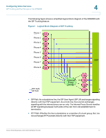
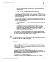
Configuring Voice Services SIP Trunking and Hunt Groups on the SPA8000 4 The following figure shows a simplified logical block diagram of the SPA8000 with the SIP Trunking feature. Figure 1 Logical Block Diagram of SIP Trunking Phone 1 L1 Phone 2 L2 Phone 3 L3 Phone 4 L4 Phone 5 L5 Phone 6 L6 ITSP Phone 7 L7 Phone 8 L8 RTP Path SIP Path T1 Internal T2 Proxy Server T3 T4 • SIP Path: As a standalone line, the SIP User Agent (SIP UA) exchanges signaling directly with the ITSP equipment. As a trunk line, the Line UA exchanges signaling with the internal proxy server only. The Internal Proxy Server handles all SIP signalling between both ends of the call, from call establishment to termination. • RTP Path: Whether the line is standalone or a member of a trunk group, the Line UA exchanges RTP packets directly with the ITSP equipment. Cisco Small Business ATA Administration Guide 77
-
 1
1 -
2
-
3
-
4
-
5
-
6
-
7
-
8
-
9
-
10
-
11
-
12
-
13
-
14
-
15
-
16
-
17
-
18
-
19
-
20
-
21
-
22
-
23
-
24
-
25
-
26
-
27
-
28
-
29
-
30
-
31
-
32
-
33
-
34
-
35
-
36
-
37
-
38
-
39
-
40
-
41
-
42
-
43
-
44
-
45
-
46
-
47
-
48
-
49
-
50
-
51
-
52
-
53
-
54
-
55
-
56
-
57
-
58
-
59
-
60
-
61
-
62
-
63
-
64
-
65
-
66
-
67
-
68
-
69
-
70
-
71
-
 72
72 -
 73
73 -
 74
74 -
 75
75 -
 76
76 -
 77
77 -
 78
78 -
 79
79 -
 80
80 -
 81
81 -
 82
82 -
83
-
84
-
85
-
86
-
87
-
88
-
89
-
90
-
91
-
92
-
93
-
94
-
95
-
96
-
97
-
98
-
99
-
100
-
101
-
102
-
103
-
104
-
105
-
106
-
107
-
108
-
109
-
110
-
111
-
112
-
113
-
114
-
115
-
116
-
117
-
118
-
119
-
120
-
121
-
122
-
123
-
124
-
125
-
126
-
127
-
128
-
129
-
130
-
131
-
132
-
133
-
134
-
135
-
136
-
137
-
138
-
139
-
140
-
141
-
142
-
143
-
144
-
145
-
146
-
147
-
148
-
149
-
150
-
151
-
152
-
153
-
154
-
155
-
156
-
157
-
158
-
159
-
160
-
161
-
162
-
163
-
164
-
165
-
166
-
167
-
168
-
169
-
170
-
171
-
172
-
173
-
174
-
175
-
176
-
177
-
178
-
179
-
180
-
181
-
182
-
183
-
184
-
185
-
186
-
187
-
188
-
189
-
190
-
191
-
192
-
193
-
194
-
195
-
196
-
197
-
198
-
199
-
200
-
201
-
202
-
203
-
204
-
205
-
206
-
207
-
208
-
209
-
210
-
211
-
212
-
213
-
214
-
215
-
216
-
217
-
218
-
219
-
220
-
221
-
222
-
223
-
224
-
225
-
226
-
227
-
228
-
229
-
230
-
231
-
232
-
233
-
234
-
235
-
236
-
237
-
238
-
239
 |
 |
