Cisco WS-C2950-24 Hardware Installation Guide - Page 93
Mounting the Chassis in a Rack Typical, Rear Forward, to support the weight of the unit.
 |
View all Cisco WS-C2950-24 manuals
Add to My Manuals
Save this manual to your list of manuals |
Page 93 highlights
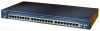
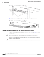
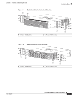
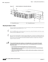
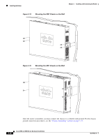
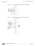
Chapter 3 Installing and Connecting the Router Installing the Router Warning To prevent personal injury or damage to the chassis, never attempt to lift or tilt the chassis using the handles on modules (such as power supplies, fans, or cards); these types of handles are not designed to support the weight of the unit. Statement 1032 Caution Be sure to leave space above and below each router in a rack to allow for cooling air circulation. Figure 3-12 shows a typical installation in a rack. Figure 3-12 Mounting the Chassis in a Rack (Typical) 250911 SYS ACT POE RPS PS Cisco 2900 Series 1 1 Mounting screws (4) Figure 3-13 shows an installation with a chassis rear-forward. Figure 3-13 Mounting the Chassis in a Rack, Rear Forward DNOENTOWTORREKMOOPVEERDATUIROINNG DNOENTOWTORREKMOOPVEERDATUIROINNG 1 1 Mounting screws (4) OL-18712-01 Cisco 2900 and 3900 Series Hardware Installation 3-11 250914
-
 1
1 -
2
-
3
-
4
-
5
-
6
-
7
-
8
-
9
-
10
-
11
-
12
-
13
-
14
-
15
-
16
-
17
-
18
-
19
-
20
-
21
-
22
-
23
-
24
-
25
-
26
-
27
-
28
-
29
-
30
-
31
-
32
-
33
-
34
-
35
-
36
-
37
-
38
-
39
-
40
-
41
-
42
-
43
-
44
-
45
-
46
-
47
-
48
-
49
-
50
-
51
-
52
-
53
-
54
-
55
-
56
-
57
-
58
-
59
-
60
-
61
-
62
-
63
-
64
-
65
-
66
-
67
-
68
-
69
-
70
-
71
-
72
-
73
-
74
-
75
-
76
-
77
-
78
-
79
-
80
-
81
-
82
-
83
-
84
-
85
-
86
-
87
-
 88
88 -
 89
89 -
 90
90 -
 91
91 -
 92
92 -
 93
93 -
 94
94 -
 95
95 -
 96
96 -
 97
97 -
 98
98 -
99
-
100
-
101
-
102
-
103
-
104
-
105
-
106
-
107
-
108
-
109
-
110
-
111
-
112
-
113
-
114
-
115
-
116
-
117
-
118
-
119
-
120
-
121
-
122
-
123
-
124
-
125
-
126
-
127
-
128
-
129
-
130
-
131
-
132
-
133
-
134
-
135
-
136
-
137
-
138
-
139
-
140
-
141
-
142
-
143
-
144
-
145
-
146
-
147
-
148
-
149
-
150
-
151
-
152
-
153
-
154
-
155
-
156
-
157
-
158
-
159
-
160
-
161
-
162
-
163
-
164
-
165
-
166
-
167
-
168
-
169
-
170
-
171
-
172
-
173
-
174
-
175
-
176
-
177
-
178
-
179
-
180
-
181
-
182
-
183
-
184
-
185
-
186
-
187
-
188
-
189
-
190
-
191
-
192
-
193
-
194
-
195
-
196
-
197
-
198
-
199
-
200
-
201
-
202
-
203
-
204
-
205
-
206
-
207
-
208
-
209
-
210
-
211
-
212
-
213
-
214
-
215
-
216
-
217
-
218
-
219
-
220
 |
 |