Cisco WS-C2950T-24 Hardware Installation Guide - Page 167
Installing a DRAM DIMM, Step 1, Caution
 |
View all Cisco WS-C2950T-24 manuals
Add to My Manuals
Save this manual to your list of manuals |
Page 167 highlights
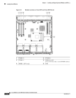
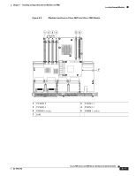
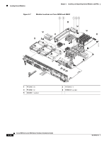
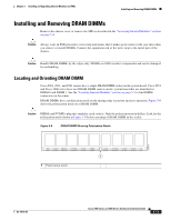
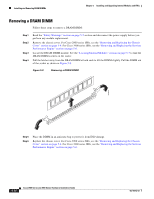
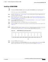
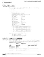
Chapter 5 Installing and Upgrading Internal Modules and FRUs Installing and Removing DRAM DIMMs Installing a DRAM DIMM Note Unregistered DIMMS (UDIMMs) and very low profile (VLP) RDIMMs are not interchangeable. Follow these steps to install a DRAM DIMM: Step 1 Step 2 Step 3 Step 4 Step 5 Read the "Safety Warnings" section on page 5-2 section and disconnect the power supply before you perform any module replacement. Remove the chassis cover. For Cisco 2900 series ISRs, see the "Removing and Replacing the Chassis Cover" section on page 5-4. For Cisco 3900 series ISRs, see the "Removing and Replacing the Services Performance Engine" section on page 5-6. Locate the DRAM DIMM module. See the "Locating Internal Modules" section on page 5-7 to find the DRAM DIMM sockets on the router. Make sure that both latches on the DIMM connector are in the open position. Orient the DIMM so that the polarization notch lines up with the polarization key on the connector. See Figure 5-10. Caution DIMMs and PVDM3s plug into similarly sized sockets. Only the polarization notch differs. Look for the polarization notch shown in Figure 5-10 before inserting a DRAM DIMM in the socket. Figure 5-10 DRAM DIMM Showing Polarization Notch 250944 Step 6 Step 7 1 Insert the DIMM into the connector. Carefully and firmly press the DRAM DIMM into the connector until the latches close onto the DIMM. Make sure that both latches rotate to the closed position against the DIMM. See Figure 5-11. OL-18712-03 Cisco 2900 Series and 3900 Series Hardware Installation Guide 5-15
-
 1
1 -
2
-
3
-
4
-
5
-
6
-
7
-
8
-
9
-
10
-
11
-
12
-
13
-
14
-
15
-
16
-
17
-
18
-
19
-
20
-
21
-
22
-
23
-
24
-
25
-
26
-
27
-
28
-
29
-
30
-
31
-
32
-
33
-
34
-
35
-
36
-
37
-
38
-
39
-
40
-
41
-
42
-
43
-
44
-
45
-
46
-
47
-
48
-
49
-
50
-
51
-
52
-
53
-
54
-
55
-
56
-
57
-
58
-
59
-
60
-
61
-
62
-
63
-
64
-
65
-
66
-
67
-
68
-
69
-
70
-
71
-
72
-
73
-
74
-
75
-
76
-
77
-
78
-
79
-
80
-
81
-
82
-
83
-
84
-
85
-
86
-
87
-
88
-
89
-
90
-
91
-
92
-
93
-
94
-
95
-
96
-
97
-
98
-
99
-
100
-
101
-
102
-
103
-
104
-
105
-
106
-
107
-
108
-
109
-
110
-
111
-
112
-
113
-
114
-
115
-
116
-
117
-
118
-
119
-
120
-
121
-
122
-
123
-
124
-
125
-
126
-
127
-
128
-
129
-
130
-
131
-
132
-
133
-
134
-
135
-
136
-
137
-
138
-
139
-
140
-
141
-
142
-
143
-
144
-
145
-
146
-
147
-
148
-
149
-
150
-
151
-
152
-
153
-
154
-
155
-
156
-
157
-
158
-
159
-
160
-
161
-
 162
162 -
 163
163 -
 164
164 -
 165
165 -
 166
166 -
 167
167 -
 168
168 -
 169
169 -
 170
170 -
 171
171 -
 172
172 -
173
-
174
-
175
-
176
-
177
-
178
-
179
-
180
-
181
-
182
-
183
-
184
-
185
-
186
-
187
-
188
-
189
-
190
-
191
-
192
-
193
-
194
-
195
-
196
-
197
-
198
-
199
-
200
-
201
-
202
-
203
-
204
-
205
-
206
-
207
-
208
-
209
-
210
-
211
-
212
-
213
-
214
-
215
-
216
-
217
-
218
-
219
-
220
 |
 |
