Cisco WS-C2950T-24 Hardware Installation Guide - Page 95
Mounting a Cisco 2901 or 2911 Router on a Wall, Attaching Brackets to the Router for Wall Mounting
 |
View all Cisco WS-C2950T-24 manuals
Add to My Manuals
Save this manual to your list of manuals |
Page 95 highlights
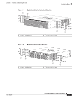
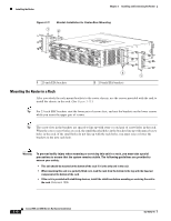
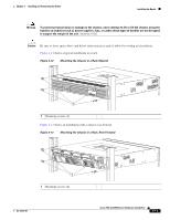
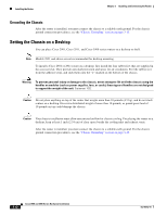
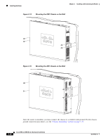
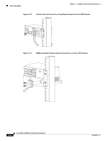
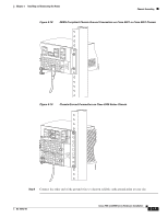
Chapter 3 Installing and Connecting the Router Installing the Router Mounting a Cisco 2901 or 2911 Router on a Wall This section explains how to mount Cisco 2901 and Cisco 2911 routers on a wall or other vertical surface. We do not recommend mounting a Cisco 2921, 2951, or Cisco 3900 series router on a wall. The following warning applies to Cisco 2901 and 2911 routers: Warning This unit is intended to be mounted on a wall. Please read the wall mounting instructions carefully before beginning installation. Failure to use the correct hardware or to follow the correct procedures could result in a hazardous situation to people and damage to the system. Statement 248 Tip When choosing a wall-mounting location, consider cable limitations and wall structure. Note The Cisco 2901 and Cisco 2911 routers use brackets designed for the 19-inch EIA rack-mounting, the part number 700-16559-01 is stamped on the bracket (shown in Figure 3-15). Attaching Brackets to the Router for Wall Mounting Attach the standard brackets to the chassis using the four screws provided for each bracket. Attaching the Router to a Wall Attach the router to the wall using the brackets previously attached. Use attachment hardware that you provide as follows: • For attaching to a wall stud, each bracket requires two number-10 wood screws (round- or pan-head) with number-10 washers, or two number-10 washer-head screws. The screws must be long enough to penetrate at least 1.5 inches (38.1 mm) into the supporting wood or metal wall stud. • For hollow-wall mounting, each bracket requires two wall anchors with washers. Wall anchors and washers must be size number 10. • Route the cables so that they do not put a strain on the connectors or mounting hardware. • The NEBS air baffle (Cisco 2911) should not be used when wall-mounting the router. Caution This unit is intended to be mounted on a wall. Please read the wall mounting instructions carefully before beginning installation. Failure to use the correct hardware or to follow the correct procedures could result in a hazardous situation to people and damage to the system. Caution The router must be mounted with the power connections oriented downward. Failure to do so could present a fire hazard. Figure 3-14 and Figure 3-15 show typical wall-mounted installations. OL-18712-01 Cisco 2900 and 3900 Series Hardware Installation 3-13
-
 1
1 -
2
-
3
-
4
-
5
-
6
-
7
-
8
-
9
-
10
-
11
-
12
-
13
-
14
-
15
-
16
-
17
-
18
-
19
-
20
-
21
-
22
-
23
-
24
-
25
-
26
-
27
-
28
-
29
-
30
-
31
-
32
-
33
-
34
-
35
-
36
-
37
-
38
-
39
-
40
-
41
-
42
-
43
-
44
-
45
-
46
-
47
-
48
-
49
-
50
-
51
-
52
-
53
-
54
-
55
-
56
-
57
-
58
-
59
-
60
-
61
-
62
-
63
-
64
-
65
-
66
-
67
-
68
-
69
-
70
-
71
-
72
-
73
-
74
-
75
-
76
-
77
-
78
-
79
-
80
-
81
-
82
-
83
-
84
-
85
-
86
-
87
-
88
-
89
-
 90
90 -
 91
91 -
 92
92 -
 93
93 -
 94
94 -
 95
95 -
 96
96 -
 97
97 -
 98
98 -
 99
99 -
 100
100 -
101
-
102
-
103
-
104
-
105
-
106
-
107
-
108
-
109
-
110
-
111
-
112
-
113
-
114
-
115
-
116
-
117
-
118
-
119
-
120
-
121
-
122
-
123
-
124
-
125
-
126
-
127
-
128
-
129
-
130
-
131
-
132
-
133
-
134
-
135
-
136
-
137
-
138
-
139
-
140
-
141
-
142
-
143
-
144
-
145
-
146
-
147
-
148
-
149
-
150
-
151
-
152
-
153
-
154
-
155
-
156
-
157
-
158
-
159
-
160
-
161
-
162
-
163
-
164
-
165
-
166
-
167
-
168
-
169
-
170
-
171
-
172
-
173
-
174
-
175
-
176
-
177
-
178
-
179
-
180
-
181
-
182
-
183
-
184
-
185
-
186
-
187
-
188
-
189
-
190
-
191
-
192
-
193
-
194
-
195
-
196
-
197
-
198
-
199
-
200
-
201
-
202
-
203
-
204
-
205
-
206
-
207
-
208
-
209
-
210
-
211
-
212
-
213
-
214
-
215
-
216
-
217
-
218
-
219
-
220
 |
 |
