Cisco WS-C2950T-24 Hardware Installation Guide - Page 25
Back Panel of the Cisco 2911 Router
 |
View all Cisco WS-C2950T-24 manuals
Add to My Manuals
Save this manual to your list of manuals |
Page 25 highlights
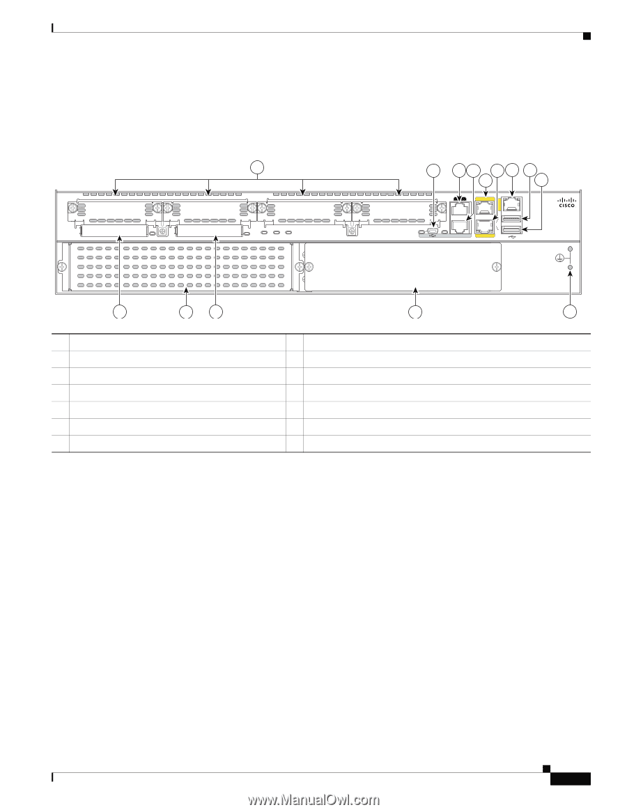
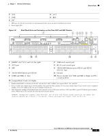
250972 Chapter 1 Overview of the Routers Chassis Views 1. LED goes off if the AC power fails or is disconnected. It does not go on and off with the power switch 2. RPS = Redundant Power Supply 3. PS = power supply Figure 1-5 Back Panel of the Cisco 2911 Router 1 EHWIC 3 EHWIC 2 EHWIC 1 DO NOT REMOVE DURING NETWORKING OPERATION CF 1 DO NOT REMOVE DURING NETWORKING OPERATION CF 0 ISM PVDM1 PVDM0 EHWIC 0 2 34 65 9 7 8 S L AUX GE 0/2 G S L E 0 / 0 1 USB EN EN 0 CONSOLE GE 0/1 2911 12 13 12 11 10 1 EHWIC slots1 0, 1, 2, and 3 (0, Far right) 2 USB serial port 3 AUX 4 RJ-45 serial console port 5 10/100/1000 Ethernet port (GE0/0) 6 10/100/1000 Ethernet port (GE0/1) 7 10/100/1000 Ethernet port (GE0/2) 8 USB 0 9 USB 1 11 AC or DC or AC-POE Power Module 13 Service module3 slot 1 10 Ground 12 CompactFlash2 0 and 1 (0, Right) 1. Double-wide EHWICs can fit into slot 0 and 1, and into slot 2 and 3. EHWIC slots support HWIC, VIC, and WIC. 2. Only Advanced Capability CompactFlash (CF) purchased from Cisco operates in Cisco 2900 series and Cisco 3900 series ISRs. Legacy CF can impact and several degrade performance in these routers. See the "Memory" section on page 1-21. When legacy CF is inserted, the following error message appears: WARNING: Unsupported compact flash detected. Use of this card during normal operation can impact and severely degrade performance of the system. Please use supported compact flash cards only. 3. Service module slots support legacy network modules when inserted with an adapter. See the router product page at Cisco.com for a list of supported modules. OL-18712-02 Cisco 2900 Series and 3900 Series Hardware Installation Guide 1-5
-
 1
1 -
2
-
3
-
4
-
5
-
6
-
7
-
8
-
9
-
10
-
11
-
12
-
13
-
14
-
15
-
16
-
17
-
18
-
19
-
 20
20 -
 21
21 -
 22
22 -
 23
23 -
 24
24 -
 25
25 -
 26
26 -
 27
27 -
 28
28 -
 29
29 -
 30
30 -
31
-
32
-
33
-
34
-
35
-
36
-
37
-
38
-
39
-
40
-
41
-
42
-
43
-
44
-
45
-
46
-
47
-
48
-
49
-
50
-
51
-
52
-
53
-
54
-
55
-
56
-
57
-
58
-
59
-
60
-
61
-
62
-
63
-
64
-
65
-
66
-
67
-
68
-
69
-
70
-
71
-
72
-
73
-
74
-
75
-
76
-
77
-
78
-
79
-
80
-
81
-
82
-
83
-
84
-
85
-
86
-
87
-
88
-
89
-
90
-
91
-
92
-
93
-
94
-
95
-
96
-
97
-
98
-
99
-
100
-
101
-
102
-
103
-
104
-
105
-
106
-
107
-
108
-
109
-
110
-
111
-
112
-
113
-
114
-
115
-
116
-
117
-
118
-
119
-
120
-
121
-
122
-
123
-
124
-
125
-
126
-
127
-
128
-
129
-
130
-
131
-
132
-
133
-
134
-
135
-
136
-
137
-
138
-
139
-
140
-
141
-
142
-
143
-
144
-
145
-
146
-
147
-
148
-
149
-
150
-
151
-
152
-
153
-
154
-
155
-
156
-
157
-
158
-
159
-
160
-
161
-
162
-
163
-
164
-
165
-
166
-
167
-
168
-
169
-
170
-
171
-
172
-
173
-
174
-
175
-
176
-
177
-
178
-
179
-
180
-
181
-
182
-
183
-
184
-
185
-
186
-
187
-
188
-
189
-
190
-
191
-
192
-
193
-
194
-
195
-
196
-
197
-
198
-
199
-
200
-
201
-
202
-
203
-
204
-
205
-
206
-
207
-
208
-
209
-
210
-
211
-
212
-
213
-
214
-
215
-
216
-
217
-
218
-
219
-
220
 |
 |