Cisco WS-C3750G-24TS-S1U Getting Started Guide - Page 5
Step 7, Connect a Category 5 Ethernet cable - catalyst
 |
UPC - 746320953410
View all Cisco WS-C3750G-24TS-S1U manuals
Add to My Manuals
Save this manual to your list of manuals |
Page 5 highlights
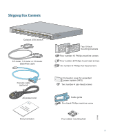
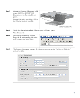
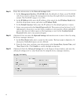
Step 7 Connect a Category 5 Ethernet cable to any 10/100 or 10/100/1000 Ethernet port on the switch front panel. Connect the other end of the cable to the Ethernet port on your PC. SYST RPS MASTR STAT DUPLX SPEED STACK MODE 1 1X 2X 23 45 67 89 10 11 12 13 14 15 16 17 15X 17X 16X 18X 18 19 20 21 22 23 24 25 26 27 28 29 30 31 32 33 31X 33X 34 35 36 37 38 39 40 41 42 43 44 45 46 47 48 Catalyst 3560G SERIES PoE-48 47X 32X 34X 49 51 48X 50 52 Step 8 Step 9 Verify that the switch and PC Ethernet ports LEDs are green. Wait 30 seconds. Start a web browser on your PC. Enter the IP address 10.0.0.1 in the web browser, and press Enter. DHCP-enabled PC Step 10 The Express Setup page appears. If it does not appear, see the "In Case of Difficulty" section for help. 5
-
 1
1 -
 2
2 -
 3
3 -
 4
4 -
 5
5 -
 6
6 -
 7
7 -
 8
8 -
 9
9 -
 10
10 -
 11
11 -
12
-
13
-
14
-
15
-
16
-
17
-
18
-
19
-
20
-
21
-
22
-
23
-
24
-
25
-
26
 |
 |
