Cisco WS-C4928-10GE Installation Guide - Page 33
Chassis Cooling
 |
View all Cisco WS-C4928-10GE manuals
Add to My Manuals
Save this manual to your list of manuals |
Page 33 highlights
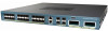
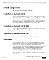
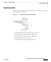
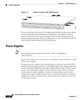
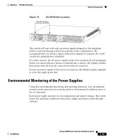
Chapter 1 Product Overview Switch Components Table 1-1 LED Functions (continued) LED Color or State Description FAN Off Green Red No power to the switch or fans (the tray may not be plugged in especially if one or more of the power supplies status LED is green) Fan tray operational Fault detected PS1 and PS2 Off Green Red No power to the PS Operational1 Fault detected or the on/off switch is set to off while the power supply is plugged in 1. If either LED is green and the other is OFF the power supply is probably not plugged in. If it is red, the supply is either plugged in and not switched on or it is faulty. It may be necessary to use the CLI for further status information. Chassis Cooling Note For environmental specifications, see Chapter 2, "Site Planning." The hot-swappable system fan tray provides cooling air for the internal chassis components. The fans exhaust air to the rear, and fresh air is drawn in from the sides of the chassis. Caution When the fan tray is removed, internal circuitry is exposed that should not be touched by tools or fingers. The system should not be left operating without a fan tray for longer than is necessary to replace a faulty fan tray with a new one. Figure 1-8 shows the direction of airflow going in and out of the switch. 78-18039-02 Catalyst 4900 Series Switch Installation Guide 1-11
-
 1
1 -
2
-
3
-
4
-
5
-
6
-
7
-
8
-
9
-
10
-
11
-
12
-
13
-
14
-
15
-
16
-
17
-
18
-
19
-
20
-
21
-
22
-
23
-
24
-
25
-
26
-
27
-
 28
28 -
 29
29 -
 30
30 -
 31
31 -
 32
32 -
 33
33 -
 34
34 -
 35
35 -
 36
36 -
 37
37 -
 38
38 -
39
-
40
-
41
-
42
-
43
-
44
-
45
-
46
-
47
-
48
-
49
-
50
-
51
-
52
-
53
-
54
-
55
-
56
-
57
-
58
-
59
-
60
-
61
-
62
-
63
-
64
-
65
-
66
-
67
-
68
-
69
-
70
-
71
-
72
-
73
-
74
-
75
-
76
-
77
-
78
-
79
-
80
-
81
-
82
-
83
-
84
-
85
-
86
-
87
-
88
-
89
-
90
-
91
-
92
-
93
-
94
-
95
-
96
-
97
-
98
-
99
-
100
-
101
-
102
-
103
-
104
-
105
-
106
-
107
-
108
-
109
-
110
-
111
-
112
-
113
-
114
-
115
-
116
-
117
-
118
-
119
-
120
-
121
-
122
-
123
-
124
-
125
-
126
-
127
-
128
-
129
-
130
-
131
-
132
-
133
-
134
-
135
-
136
-
137
-
138
-
139
-
140
-
141
-
142
 |
 |
