Cisco WS-C4928-10GE Installation Guide - Page 70
Getting Started, Problem Solving to the System Component Level
 |
View all Cisco WS-C4928-10GE manuals
Add to My Manuals
Save this manual to your list of manuals |
Page 70 highlights
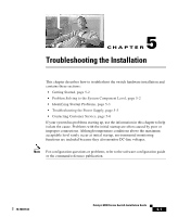
Getting Started Chapter 5 Troubleshooting the Installation Getting Started When the initial system boot is complete, verify the following: • Power supplies are supplying power to the system. • The system fan assembly is operating. • System software boots successfully. If all of these conditions are met and the hardware installation is complete, refer to the Software Configuration Guide and the Command Reference publications to troubleshoot the software. However, if any of these conditions are not met, use the procedures in this chapter to isolate and, if possible, resolve the problem. Problem Solving to the System Component Level The key to success when troubleshooting the system is to isolate the problem to a specific system component. The first step is to compare what the system is doing to what it should be doing. Because a startup problem can usually be attributed to a single component, it is more efficient to isolate the problem to a subsystem rather than troubleshoot each separate component in the system. The switch consists of the following subsystems: • Power supply-Includes the power supply and power supply cooling. (See the "Troubleshooting the Power Supply" section on page 5-5.) • Fan assembly system-The chassis fan assembly should operate whenever system power is on. Usually, it continues to operate even when the environmental monitor shuts down the system because of an overtemperature or overvoltage condition. (It will shut down for a power supply shutdown.) You should be able to hear the fan assembly to determine whether or not it is operating. If the FAN LED is orange and you determine that the fan assembly is not operating, you should immediately contact a customer service representative. There are no installation adjustments that you can make if the fan assembly does not function properly at the initial startup. Catalyst 4900 Series Switch Installation Guide 5-2 78-18039-02
-
 1
1 -
2
-
3
-
4
-
5
-
6
-
7
-
8
-
9
-
10
-
11
-
12
-
13
-
14
-
15
-
16
-
17
-
18
-
19
-
20
-
21
-
22
-
23
-
24
-
25
-
26
-
27
-
28
-
29
-
30
-
31
-
32
-
33
-
34
-
35
-
36
-
37
-
38
-
39
-
40
-
41
-
42
-
43
-
44
-
45
-
46
-
47
-
48
-
49
-
50
-
51
-
52
-
53
-
54
-
55
-
56
-
57
-
58
-
59
-
60
-
61
-
62
-
63
-
64
-
 65
65 -
 66
66 -
 67
67 -
 68
68 -
 69
69 -
 70
70 -
 71
71 -
 72
72 -
 73
73 -
 74
74 -
 75
75 -
76
-
77
-
78
-
79
-
80
-
81
-
82
-
83
-
84
-
85
-
86
-
87
-
88
-
89
-
90
-
91
-
92
-
93
-
94
-
95
-
96
-
97
-
98
-
99
-
100
-
101
-
102
-
103
-
104
-
105
-
106
-
107
-
108
-
109
-
110
-
111
-
112
-
113
-
114
-
115
-
116
-
117
-
118
-
119
-
120
-
121
-
122
-
123
-
124
-
125
-
126
-
127
-
128
-
129
-
130
-
131
-
132
-
133
-
134
-
135
-
136
-
137
-
138
-
139
-
140
-
141
-
142
 |
 |
