Compaq Armada e500s Compaq ArmadaStation EM Maintenance and Service Guide - Page 47
half-height bay., Install the four screws
 |
View all Compaq Armada e500s manuals
Add to My Manuals
Save this manual to your list of manuals |
Page 47 highlights
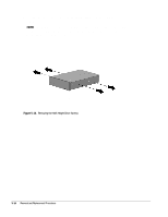
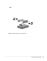
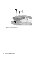
10. Align the front cover of the half-height drive with the tab on the front of the bezel cage – (Figure 5-17). NOTE: The bezel cage should be aligned so the "L" and "LEFT" indicators can be read when the half-height drive is installed in the expansion base left half-height bay. 11. Install the four screws — that secure the half-height drive to the bezel cage. Figure 5-17. Attaching the Bezel Cage to the Half-Height Drive Removal and Replacement Procedures 5-17
-
 1
1 -
2
-
3
-
4
-
5
-
6
-
7
-
8
-
9
-
10
-
11
-
12
-
13
-
14
-
15
-
16
-
17
-
18
-
19
-
20
-
21
-
22
-
23
-
24
-
25
-
26
-
27
-
28
-
29
-
30
-
31
-
32
-
33
-
34
-
35
-
36
-
37
-
38
-
39
-
40
-
41
-
 42
42 -
 43
43 -
 44
44 -
 45
45 -
 46
46 -
 47
47 -
 48
48 -
 49
49 -
 50
50 -
 51
51 -
 52
52 -
53
-
54
-
55
-
56
-
57
-
58
-
59
-
60
-
61
-
62
-
63
-
64
-
65
-
66
-
67
-
68
-
69
-
70
-
71
-
72
-
73
-
74
 |
 |

Removal and Replacement Procedures
5-17
10. Align the front cover of the half-height drive with the tab on the front of the bezel
cage
(Figure 5-17).
NOTE:
The bezel cage should be aligned so the “L” and “LEFT” indicators can
be read when the half-height drive is installed in the expansion base left
half-height bay.
11. Install the four screws
that secure the half-height drive to the bezel cage.
Figure 5-17.
Attaching the Bezel Cage to the Half-Height Drive