Compaq Armada e500s Compaq ArmadaStation EM Maintenance and Service Guide - Page 73
Miscellaneous Cable Kit, PCI CardBus Reader
 |
View all Compaq Armada e500s manuals
Add to My Manuals
Save this manual to your list of manuals |
Page 73 highlights
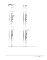
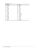
microphone jack illustrated, 1-4 pinout, A-1 Miscellaneous Cable Kit cable illustrated, 3-2 monitor carbon spare part number, 3-6 connector illustrated, 1-5 pinout, 1-3 latch slot illustrated, 1-5 monitor support cover recess illustrated, 1-3 monitor support cover specification, 6-1 mouse connector illustrated, 1-5 pinout, A-2 MultiBay, 1-6 activity light, 1-6 bottom illustrated, 1-3 light illustrated, 1-3 release button illustrated, 1-3 buttons illustrated, 3-4 illustrated, 3-2 Option Cable Kit illustrated, 3-5 spare part number, 3-3, 3-5 removing, 5-24 spare part number, 3-3 top illustrated, 1-3 light illustrated, 1-3 release button illustrated, 1-3 O operating current specification, 6-1 operating voltage specification, 6-1 P parallel connector illustrated, 1-5 pinout, A-2 PC Card inserting, 5-11 PCI card slots illustrated, 1-4 PCI CardBus Reader inserting, 5-11 spare part number, 3-6 PCI expansion board, 1-7 installing, 5-9 plastic parts, 4-7 Plastics Kit components illustrated, 3-4 illustrated, 3-2 spare part number, 3-3, 3-4 power button illustrated, 1-4 connector illustrated, 1-5 cord spare part number, 3-3 disconnecting, 5-3 supply illustrated, 3-2 removing, 5-29 spare part number, 3-3 supply cable disconnecting, 5-29 power/suspend light, 1-6 illustrated, 1-3 preparing for disassembly, 5-3 preventing damage to drives, 4-3 preventing electrostatic damage, 4-2 R rated current specification, 6-1 rated line frequency specification, 6-1 rated voltage specification, 6-1 rear bezel illustrated, 3-2 spare part number, 3-3 rear panel release latch illustrated, 1-5 retaining latch illustrated, 1-3 Return Kit spare part number, 3-6 S Screw Kit spare part number, 3-6 screws, 4-6 security cable slot illustrated, 1-5 security lock, 1-7 serial connector illustrated, 1-5 pinout, A-2 serial number, vi location, 3-1, 5-1 service considerations, 4-6 shock specification, 6-1 software required for service, 4-6 speaker left illustrated, 3-2 removing, 5-23 spare part number, 3-3 static generating, 4-2 preventing materials, 4-5 shielding protection levels, 4-3 I-2 Index
-
 1
1 -
2
-
3
-
4
-
5
-
6
-
7
-
8
-
9
-
10
-
11
-
12
-
13
-
14
-
15
-
16
-
17
-
18
-
19
-
20
-
21
-
22
-
23
-
24
-
25
-
26
-
27
-
28
-
29
-
30
-
31
-
32
-
33
-
34
-
35
-
36
-
37
-
38
-
39
-
40
-
41
-
42
-
43
-
44
-
45
-
46
-
47
-
48
-
49
-
50
-
51
-
52
-
53
-
54
-
55
-
56
-
57
-
58
-
59
-
60
-
61
-
62
-
63
-
64
-
65
-
66
-
67
-
 68
68 -
 69
69 -
 70
70 -
 71
71 -
 72
72 -
 73
73 -
 74
74
 |
 |