Cub Cadet CC 800 Operation Manual - Page 10
Unfolding the Handle, Attaching the Shift Lever, Checking Tire Pressure
 |
View all Cub Cadet CC 800 manuals
Add to My Manuals
Save this manual to your list of manuals |
Page 10 highlights
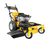
Unfolding the Handle 1. Remove the star knobs (a) and carriage screws (b) from the lower handle. See Figure 3-3. (a) (b) (c) (b) (a) (a) (d) (b) Figure 3-3 2. Pivot the upper handle into operating position. Be careful not to crimp cables. See Figure 3-4. Figure 3-5 2. Remove the remaining screw (c) and nut (d) from the lower shift lever plate. See Figure 3-5. 3. Position the upper shift lever into a vertical position aligning the holes in the lever with the holes in the shift plate. See Figure 3-6. (b) (a) (a) (a) (a) (b) (b) (b) Figure 3-4 3. Reinstall the carriage screws (a) and star knobs (b) removed in Step 1. 4. Tighten the upper and lower star knobs and carriage screws to secure the upper handle to the lower handle. See Figure 3-4. 5. The handle height can be adjusted to any of three positions. For instructions, refer to Handle Height in the Maintenance and Adjustments section on page 21 of this manual. Attaching the Shift Lever 1. Remove the screw (a) and lock nut (b) that secures the shift lever to the shift lever plate. See Figure 3-5. Figure 3-6 4. Secure the lever to the plate using the two screws (a) and two nuts (b) removed in Steps 1 and 2. See Figure 3-6 inset. Checking Tire Pressure WARNING! Under any circumstance do not exceed manufacturer's recommended psi. Equal tire pressure should be maintained at all times. Refer to sidewall of tire for recommended pressure. The rear tires on your unit may be over-inflated for shipping purposes. Reduce the tire pressure before operating the mower. Refer to the tire side wall for tire manufacturer's recommended psi and deflate (or inflate) the tires as necessary. 10 Section 2 - Assembly & Set-Up
-
 1
1 -
2
-
3
-
4
-
 5
5 -
 6
6 -
 7
7 -
 8
8 -
 9
9 -
 10
10 -
 11
11 -
 12
12 -
 13
13 -
 14
14 -
 15
15 -
16
-
17
-
18
-
19
-
20
-
21
-
22
-
23
-
24
-
25
-
26
-
27
-
28
-
29
-
30
-
31
-
32
 |
 |
