D-Link DFL-80 User Manual
D-Link DFL-80 Manual
 |
View all D-Link DFL-80 manuals
Add to My Manuals
Save this manual to your list of manuals |
D-Link DFL-80 manual content summary:
- D-Link DFL-80 | User Manual - Page 1
D-Link DFL-80 Ethernet VPN Firewall Manual Building Networks for People - D-Link DFL-80 | User Manual - Page 2
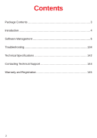
Contents Package Contents 3 Introduction 4 Software Management 6 Troubleshooting 134 Technical Specifications 142 Contacting Technical Support 144 Warranty and Registration 145 2 - D-Link DFL-80 | User Manual - Page 3
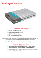
Package Contents Contents of Package: D-Link DFL-80 Firewall Manual and Warranty on CD Quick Installation Guide AC power adapter (5V, 3A) Note: Using a power supply with a different voltage rating than the one included with the DFL-80 will cause damage and void the warranty for this product. If any - D-Link DFL-80 | User Manual - Page 4
DFL-80 security feature Some functions that are available in the firewall are: Packet Filter, Proxy Server, Intruder Alarm, Packet Monitor Log, Inbound/Outbound Policy, etc. DFL-80 immediate intruder's invasion crisis management. DFL-80 supporting protocols The DFL-80 supports all the TCP, UDP and - D-Link DFL-80 | User Manual - Page 5
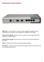
external router, DSL modem, or Cable modem. Internal Ports (LAN): Use this port to connect to the internal network of the office. Reset: Reset the DFL-80 to the original default settings. DC Power: connect one end of the power supply to this port, the other end to the electrical wall outlet. 5 - D-Link DFL-80 | User Manual - Page 6
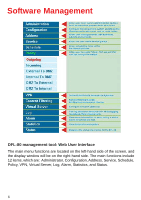
Management DFL-80 management tool: Web User Interface The main menu functions are located on the left-hand side of the screen, and the display window will be on the right-hand side. The main functions include 12 items, which are: Administrator, Configuration, Address, Service, Schedule, Policy, VPN - D-Link DFL-80 | User Manual - Page 7
sure there is a link light for the connection. The DFL-80 has an embedded web server used for management and configuration. Use a web browser to display the configurations of the firewall (such as Internet Explorer 6(or above) or Netscape 6(or above) with full java script support). The default IP - D-Link DFL-80 | User Manual - Page 8
either with an Internet Time Server or with the client computer's clock. Software Update: Administrators may visit http://support.dlink.com to download the latest firmware. Administrators may update the DFL-80 firmware to maximize its performance and stay current with the latest fixes for intruding - D-Link DFL-80 | User Manual - Page 9
Administration (continued) Firewall Administration setup On the left hand menu, click on Administration, and then select Admin below it. The . Sub Admins have read only privilege. Configure: Click Modify to change the Sub Administrator's password and click Remove to delete a Sub Administrator. 9 - D-Link DFL-80 | User Manual - Page 10
new Sub Administrator. Step 2. In the Add New Sub Administrator window: ! Sub Admin Name: Enter the username of new Sub Admin. ! Password: Enter a password for the new Sub Admin. ! Confirm Password: Enter the password again. Step 3. Click OK to add the user or click Cancel to cancel the addition. 10 - D-Link DFL-80 | User Manual - Page 11
window will appear. Enter in the required information: ! Password: enter original password. ! New Password: enter new password ! Confirm Password: enter the new password again. Step 3. Click OK to confirm password change or click Cancel to cancel it. Removing a Sub Administrator: Step 1. In the - D-Link DFL-80 | User Manual - Page 12
Settings The Administrator may use this function to backup firewall configurations and export (save) them to an "Administrator" computer or anywhere on the network; or restore a configuration file to the device; or restore the firewall back to default factory settings. Entering the Settings window: - D-Link DFL-80 | User Manual - Page 13
Exporting DFL-80 Firewall settings: Step 1. Under Firewall Configuration, click on the Download button next to Export System Settings to Client. Step 2. When the File Download pop-up window appears, choose the destination place in which to save the exported file. The Administrator may choose to - D-Link DFL-80 | User Manual - Page 14
Restoring Factory Default Settings: Step 1. Select Reset Factory Settings under Firewall Configuration. Step 2. Click OK at the bottom-right of the screen to restore the factory settings. Enabling E-mail Alert Notification: Step 1. Select Enable E-mail Alert Notification under E-Mail Settings. This - D-Link DFL-80 | User Manual - Page 15
To-Firewall Packets Log Once this function is enabled, every packet passing through the Firewall will be recorded for the administrator to trace. Firewall Reboot Once this function is enabled, the firewall will be reboot. Step 1. Click Setting in the Administration menu to enter the settings window. - D-Link DFL-80 | User Manual - Page 16
down arrow to select the offset time from GMT. Step 3. Enter the Server IP Address or Server name with which you want to synchronize. Step 4. Update system clock every 5 minutes You can set the interval time to synchronize with outside servers. If you set it to 0, it means the device will - D-Link DFL-80 | User Manual - Page 17
Software Update Under Software Update, the admin may update the DFL-80's software with a newer software. The admin can visit http://support.dlink.com to get an available updated software. Configuration System Configuration the local hard drive as shown in the Administrator section of this manual. 17 - D-Link DFL-80 | User Manual - Page 18
on the Internet. IP Address: The private IP address of the Firewall's internal network is the IP address of the Internal (LAN) ports of the DFL-80. The default IP address is 192.168.1.1. 18 - D-Link DFL-80 | User Manual - Page 19
ping the IP Address of the Firewall. If set to enable, the DFL-80 will respond to ping packets from the internal network. For PPPoE (ADSL User): This option is for PPPoE users who are required to enter a username and password in order to connect, such as ADSL users. Current Status: Displays the - D-Link DFL-80 | User Manual - Page 20
accessed from the WAN network. This will allow the WebUI to be configured from a user on the Internet. Keep in mind that the DFL-80 always requires a username and password to enter the WebUI. For Static IP Address: This option is for users who are assigned a static IP Address from their ISP. Your - D-Link DFL-80 | User Manual - Page 21
from the WAN network. This will allow the WebUI to be configured from a user on the Internet. Keep in mind that the DFL-80 always requires a username and password to enter the WebUI. DMZ Interface The Administrator uses the DMZ Interface to set up the DMZ network. The DMZ network consists of - D-Link DFL-80 | User Manual - Page 22
NAT after completing the settings; each department uses a different WAN IP Address to connect to the Internet. The settings of each department are as follows Service IP Address:192.168.2.1 Subnet Mask: 255.255.255.0 Default Gateway: 192.168.2.11 The other departments are also set by groups, this is - D-Link DFL-80 | User Manual - Page 23
Multiple NAT settings Click Multiple NAT in the Configuration menu to enter Multiple NAT window. Multiple NAT Global port interface IP Address: Global port IP Address. Local port interface IP Address: Local port IP Address and Subnet Mask. Modify: Modify the settings of Multiple NAT. Click Modify to - D-Link DFL-80 | User Manual - Page 24
Add Multiple NAT Step 1. Click Multiple NAT in the Configuration menu to enter Multiple NAT window. Step 2. Click the Add button below to add Multiple NAT. Step 3. Enter the IP Address in the appropriate column of the new window. External Interface IP: WAN IP address to be used for the Multiple NAT - D-Link DFL-80 | User Manual - Page 25
Modify Multiple NAT Step 1. Click Multiple NAT in the Configuration menu to enter Multiple NAT window. Step 2. Find the IP Address you want to modify and click Modify Step 3. Enter the new IP Address in Modify Multiple NAT window. Step 4. Click the OK button below to change the setting or click - D-Link DFL-80 | User Manual - Page 26
Hacker Alert The Administrator can enable the DFL-80's intruder alert functions in this section. When abnormal and an email alert is sent to the Administrator. The default SYN flood threshold is set to 200 Pkts/Sec . ! Detect ICMP Flood: Select this option to detect ICMP flood attacks. When intruders - D-Link DFL-80 | User Manual - Page 27
as trusted users of the network in Spoof attacks. They use a fake identity to try to pass through the Firewall System and invade the network. ! Filter IP Source Route Option: Each IP packet can carry an optional field that specifies the replying address that can be different from the source address - D-Link DFL-80 | User Manual - Page 28
Route Table In this section, the Administrator can add static routes for the networks. Entering the Route Table screen: Click Configuration on the left side menu bar, then click Route Table below it. The Route Table window appears, in which current route settings are shown. Route Table functions: - D-Link DFL-80 | User Manual - Page 29
Adding a new Static Route: Step 1. In the Route Table window, click the New Entry button. Step 2. In the Add New Static Route window, enter new static route information. Step 3. In the Interface pull-down menu, select the network to connect (Internal, External or DMZ). Step 4. Click OK to add the - D-Link DFL-80 | User Manual - Page 30
Modifying a Static Route: Step 1. In the Route Table menu, find the route to edit and click the corresponding Modify option in the Configure field. Step 2. In the Modify Static Route window, modify the necessary routing addresses. Step 3. Click OK to apply changes or click Cancel to cancel it. 30 - D-Link DFL-80 | User Manual - Page 31
DHCP In the section, the Administrator can configure DHCP (Dynamic Host Configuration Protocol) settings for the Internal (LAN) network. Entering the DHCP window: Step 1. Click Configuration on the left hand side menu bar, then click DHCP below it. The DHCP window appears in which current DHCP - D-Link DFL-80 | User Manual - Page 32
assigning to DHCP clients. (Optional) Step 6. Click OK to enable DHCP support. Step 7. Lease Time: Enter the hour for this configuration to last. DNS-Proxy The DFL-80's Administrator may use the DNS Proxy function to make the DFL-80 Firewall act as a DNS Server for the Internal and DMZ network. All - D-Link DFL-80 | User Manual - Page 33
Entering the DNS Proxy window: Click on Configuration in the menu bar, then click on DNS Proxy below it. The DNS Proxy window will appear. Below is the information needed for setting up the DNS Proxy: • Domain Name: The domain name of the server • Virtual IP Address: The virtual IP address - D-Link DFL-80 | User Manual - Page 34
Modifying a DNS Proxy: Step 1: In the DNS Proxy window, find the policy to be modified and click the corresponding Modify option in the Configure field. Step 2: Make the necessary changes needed. Step 3: Click OK to save changes or click on Cancel to cancel modifications. Removing a DNS Proxy: Step - D-Link DFL-80 | User Manual - Page 35
, the IP address in Dynamic DNS Server will be automatically updated with the new IP address provided by ISP. Click Dynamic DNS in the Configuration menu to enter Dynamic DNS window. How to use dynamic DNS. The firewall provides a list of service providers, users have to register first to use this - D-Link DFL-80 | User Manual - Page 36
fill in the external IP Check to automatically fill in the external IP. ! User Name Enter the registered user name. ! Password Enter the password provided by ISP(Internet Service Provider). ! Domain name Your host domain name provided by ISP. Step 4: Click OK to add dynamic DNS or click Cancel - D-Link DFL-80 | User Manual - Page 37
Modify Dynamic DNS Step 1: Click Dynamic DNS in the Configuration menu to enter Dynamic DNS window. Step 2: Find the item you want to change and click Modify. Step 3: Enter the new information in the Modify Dynamic DNS window. Step 4: Click OK to change the settings or click Cancel to discard - D-Link DFL-80 | User Manual - Page 38
Address The DFL-80 Firewall allows the Administrator to set Interface addresses of the Internal network, Internal network group, External network, External network group, DMZ and DMZ group. What - D-Link DFL-80 | User Manual - Page 39
Adding a new Internal Address: Step 1. In the Internal window, click the New Entry button. Step 2. In the Add New Address window, enter the settings of a new internal network address. Step 3. Click OK to add the specified internal network or click Cancel to cancel the changes. Modifying an Internal - D-Link DFL-80 | User Manual - Page 40
Removing an Internal Address: Step 1. In the Internal window, locate the name of the network to be removed. Click the Remove option in its corresponding Configure field. Step 2. In the Remove confirmation pop-up box, click OK to remove the address or click Cancel to discard changes. Internal Group - D-Link DFL-80 | User Manual - Page 41
Adding an Internal Group: Step 1. In the Internal Group window, click the New Entry button to enter the Add New Address Group window. Step 2. In the Add New Address Group window: ! Available Address: list the names of all the members of the internal network. ! Selected Address: list the names to be - D-Link DFL-80 | User Manual - Page 42
Modifying an Internal Group: Step 1. In the Internal Group window, locate the network group desired to be modified and click its corresponding Modify option in the Configure field. Step 2. A window displaying the information of the selected group appears: ! Available Address: list names of all - D-Link DFL-80 | User Manual - Page 43
Removing an Internal Group: Step 1. In the Internal Group window, locate the group to be removed and click its corresponding Remove option in the Configure field. Step 2. In the Remove confirmation pop-up box, click OK to remove the group or click Cancel to discard changes. External Entering the - D-Link DFL-80 | User Manual - Page 44
Adding a new External Address: Step 1. In the External window, click the New Entry button. Step 2. In the Add New Address window, enter the settings for a new external network address. Step 3. Click OK to add the specified external network or click Cancel to discard changes. Removing an External - D-Link DFL-80 | User Manual - Page 45
External Group Entering the External Group window: Click the External Group under the Address menu bar to enter the External window. The current settings for the external network group(s) will appear on the screen. 45 - D-Link DFL-80 | User Manual - Page 46
Adding an External Group: Step 1. In the External Group window, click the New Entry button and the Add New Address Group window will appear. Step 2. In the Add New Address Group window the following fields will appear: ! Name: enter the name of the new group. ! Available Address: List the names of - D-Link DFL-80 | User Manual - Page 47
Editing an External Group: Step 1. In the External Group window, locate the network group to be modified and click its corresponding Modify button in the Configure field. Step 2. A window displaying the information of the selected group appears: n Available Address: list the names of all the members - D-Link DFL-80 | User Manual - Page 48
Removing an External Group: Step 1. In the External Group window, locate the group to be removed and click its corresponding Modify option in the Configure field. Step 2. In the Remove confirmation pop-up box, click OK to remove the group or click Cancel to discard changes. DMZ Entering the DMZ - D-Link DFL-80 | User Manual - Page 49
Adding a new DMZ Address: Step 1. In the DMZ window, click the New Entry button. Step 2. In the Add New Address window, enter the settings for a new DMZ address. Step 3. Click OK to add the specified DMZ or click Cancel to discard changes. Modifying a DMZ Address: Step 1. In the DMZ window, locate - D-Link DFL-80 | User Manual - Page 50
Removing a DMZ Address: Step 1. In the DMZ window, locate the name of the network to be removed and click the Remove option in its corresponding Configure field. Step 2. In the Remove confirmation pop-up box, click OK to remove the address or click Cancel to discard changes. DMZ Group Entering the - D-Link DFL-80 | User Manual - Page 51
Adding a DMZ Group: Step 1. In the DMZ Group window, click the New Entry button. Step 2. In the Add New Address Group window: ! Available Address: List names of all members of the DMZ. ! Selected Address: list names to assign to a new group. Step 3. Name: Enter a name for the new group. Step 4. Add - D-Link DFL-80 | User Manual - Page 52
Modifying a DMZ Group: Step 1. In the DMZ Group window, locate the DMZ group to be modified and click its corresponding Modify button in the Configure field. Step 2. A window displaying information about the selected group appears: ! Available Address: list the names of all the members of the - D-Link DFL-80 | User Manual - Page 53
Removing a DMZ Group: Step 1. In the DMZ Group window, locate the group to be removed and click its corresponding Remove option in the Configure field. Step 2. In the Remove confirmation pop-up box, click OK to remove the group. 53 - D-Link DFL-80 | User Manual - Page 54
available network services. What is Service? TCP and UDP protocols support varieties of services, and each service consists of a TCP Port or UDP port number, such as TELNET(23), SMTP(25), POP3(110),etc. The DFL-80 Firewall defines two services: pre-defined service and custom service. The common - D-Link DFL-80 | User Manual - Page 55
the left side of the window. Click Predefined under it. A window will appear with a list of services and their associated Port numbers. Note: This list cannot be modified. Custom Entering the Custom window: Click Service on the menu bar on the left side of the window. Click Custom under it. A window - D-Link DFL-80 | User Manual - Page 56
: Step 1: In the Custom window, click the New Entry button and a new service table appears. Step 2: In the new service table: ! Service Name: This will be the name referencing the new service. ! Protocol: Enter the network protocol type to be used, such as TCP, UDP, or Other (please enter the number - D-Link DFL-80 | User Manual - Page 57
on the screen Step 3. Enter the new values. Step 4. Click OK to accept editing; or click Cancel. Removing Custom Services: Step 1. In the Custom window, locate the service to be removed. Click its corresponding Remove option in the Configure field. Step 2. In the Remove confirmation pop-up box - D-Link DFL-80 | User Manual - Page 58
Group Accessing the Group window: Click Service in the menu bar on the left hand side of the window. Click Group under it. A window will appear with a table displaying current service group settings set by the Administrator. 58 - D-Link DFL-80 | User Manual - Page 59
Groups: Step 1. In the Group window, click the New Entry button. In the Add Service Group window, the following fields will appear: ! Available Services: List all the available services. ! Selected Services: List services to be assigned to the new group. Step 2. Enter the new group name in the - D-Link DFL-80 | User Manual - Page 60
group window the following fields are displayed: ! Available Services: Lists all the available services. ! Selected Services: List services that have been assigned to the selected group. Step 3. Add new services: Select services in the Available Services list, and then click the Add>> button to add - D-Link DFL-80 | User Manual - Page 61
Removing Service Groups: Step 1. In the Group window, locate the service group to be removed and click its corresponding Remove option in the Configure field. Step 2. In the Remove confirmation pop-up box, click OK to remove the selected service group or click Cancel to cancel removing. 61 - D-Link DFL-80 | User Manual - Page 62
Schedule The DFL-80 Office Firewall allows the Administrator to configure a schedule for policies to take affect. By creating a schedule, the Administrator is allowing the Firewall policies to be - D-Link DFL-80 | User Manual - Page 63
Adding a new Schedule: Step 1: Click on the New Entry button and the Add New Schedule window will appear. Step 2: Schedule Name: Fill in a name for the new schedule. Period 1: Configure the start and stop time for the days of the week that the schedule will be active. Step 3: Click OK to save the - D-Link DFL-80 | User Manual - Page 64
Removing a Schedule: Step 1: In the Schedule window, find the policy to be removed and click the corresponding Remove option in the Configure field. Step 2: A confirmation pop-up box will appear, click on OK to remove the schedule. 64 - D-Link DFL-80 | User Manual - Page 65
, and applications are able to pass through the Firewall. What is Policy? The DFL-80 uses policies to filter packets. The policy settings are: source address, destination address, services, permission, packet log, packet statistics, and flow alarm. Based on its source addresses, a packet can be - D-Link DFL-80 | User Manual - Page 66
addresses that are specified in the External section of the Address menu, or all the External (WAN) network addresses. ! Service: Specify services provided by external network servers. ! Action: Control actions to permit or reject/deny packets from internal networks to external network - D-Link DFL-80 | User Manual - Page 67
Address window. To create a new destination address, please go to the External section under the Address menu. Service: Specified services provided by external network servers. These are services/application that are allowed to pass from the Internal network to the External network. Choose ANY for - D-Link DFL-80 | User Manual - Page 68
for source or destination address, go to the section where the selections are setup. (Source Address Internal of Address menu; Destination Address External of Address menu; Service [Predefined],[Custom] or Group under Service). Step 3: Click OK to do confirm modification or click Cancel to cancel - D-Link DFL-80 | User Manual - Page 69
, click OK to remove the policy or click Cancel to cancel removing. Enabled Monitoring function: Log: If Logging is enabled in the outgoing policy, the DFL-80 will log the traffic and event passing through the Firewall. The Administrator can click Log on the left menu bar to get the flow and - D-Link DFL-80 | User Manual - Page 70
Alarm window. Please refer to the section entitled "Alarm" for more information. Statistics: If Statistics is enabled in the outgoing policy, the DFL-80 will display the flow statistics passing through the Firewall. Note: The Administrator can also get flow statistics in Statistics. Please refer to - D-Link DFL-80 | User Manual - Page 71
addresses created in Virtual Server menu. ! Service: Services supported by Virtual Servers (or Mapped IP). ! Action: Control actions to permit or deny packets from external networks to Virtual Server/Mapped IP travelling through the DFL-80. ! Option: Specify the monitoring functions on - D-Link DFL-80 | User Manual - Page 72
address, please go to the Virtual Server menu. (Please refer to Chapter 8 for Virtual Server for details) Service: Specified services provided by internal network servers. These are services/application that are allowed to pass from the External network to the Internal network. Choose ANY for all - D-Link DFL-80 | User Manual - Page 73
Modifying Incoming Policy: Step 1: In the Incoming window, locate the name of policy desired to be modified and click its corresponding Modify option in the Configure field. Step 2: In the Modify Policy window, fill in new settings. Step 3: Click OK to save modifications or click Cancel to cancel - D-Link DFL-80 | User Manual - Page 74
menu and Mapped IP addresses of the Virtual Server menu. ! Service: Services supported by servers in DMZ network. ! Action: Control actions, to permit or deny packets from external networks to DMZ travelling through the DFL-80. ! Option: Specify the monitoring functions of packets from external - D-Link DFL-80 | User Manual - Page 75
that are allowed to pass from the External network to the DMZ network. Choose ANY for all services. To add or modify these services, please go to the Service menu. (Please refer to the section entitled Services for details) Action: Select Permit or Deny from the drop down list to allow or reject the - D-Link DFL-80 | User Manual - Page 76
Modifying an External to DMZ policy: Step 1: In the External To DMZ window, locate the name of policy desired to be modified and click its corresponding Modify option in the Configure field. Step 2: In the Modify Policy window, fill in new settings. Step 3: Click OK to do save modifications. - D-Link DFL-80 | User Manual - Page 77
section describes steps to create policies for packets and services from DMZ networks to External (WAN) networks. Service: services supported by Servers of external networks. ! Action: control actions, to permit or deny packets from the DMZ network to external networks travelling through the DFL-80 - D-Link DFL-80 | User Manual - Page 78
/application that are allowed to pass from the DMZl network to the External network. Choose ANY for all services. To add or modify these services, please go to the Service menu. Action: Select Permit or Deny from the drop down list to allow or reject the packets travelling from the specified DMZ - D-Link DFL-80 | User Manual - Page 79
the drop-down list, go to the section where the selections are setup. (Source Address, go to Internal under Address; Destination Address, go to External under Address; Service, go to Pre-defined Service, Custom or Group under Service.) Step 3: Click OK to save modifications or click Cancel to cancel - D-Link DFL-80 | User Manual - Page 80
of policy desired to be removed and click its corresponding Remove option in the Configure field. Step 2. In the Remove confirmation dialogue box, click OK. VPN The DFL-80 Firewall's VPN (Virtual Private Network) is set by the System Administrator. The System Administrator can add, modify or remove - D-Link DFL-80 | User Manual - Page 81
tunnel. ! Gateway IP: The external interface IP address of the remote Firewall. ! Destination Subnet: Destination network subnet. ! PSK/RSA: The IKE VPN must be defined with a Preshared Key. The Key may be up to 128 bytes long. ! Status: Connect/Disconnect or Connecting/Disconnecting. ! Configure - D-Link DFL-80 | User Manual - Page 82
Click the New Entry button and the VPN Auto Keyed Tunnel window will appear. Step 2: ! Preshare Key: The IKE VPN must be defined with a Preshared Key. is 168bit Triple DES-CBC. ! ESP-Authentication Method: The DFL-80 auto-selects MD5 or SHA-1 authentication algorithm. The default algorithm is - D-Link DFL-80 | User Manual - Page 83
Modify option in the Configure field. Step 2: In the Modify Policy window, fill in new settings. Step 3: Click OK to save modifications. Connecting the VPN connection: Once all the policy is created with the correct settings, click on the Connect option in the Configure field. The Status field will - D-Link DFL-80 | User Manual - Page 84
Removing Autokey IKE: Step 1. Locate the name of the Autokey IKE desired to be removed and click its corresponding Delete option in the Configure field. Step 2. In the Remove confirmation pop-up box, click OK to remove the Autokey IKE or click Cancel to cancel deleting. 84 - D-Link DFL-80 | User Manual - Page 85
PPTP Server Entering the PPTP Server window Step 1. Select VPN > PPTP Server. ! PPTP Server- Click Modify to select Enable or Disable. ! Client IP Range- 192.66.255.1-254 Displays the IP address range for PPTP - D-Link DFL-80 | User Manual - Page 86
Modifying PPTP Server Design Step 1. Select VPN > PPTP Server. Step 2. Click Modify after the Client IP Range. Step 3. In the Modify Server Design Window, enter appropriate settings. ! Disable PPTP- Check to disable - D-Link DFL-80 | User Manual - Page 87
Adding PPTP Server Step 1. Select VPN > PPTP Server. Click New Entry. Step 2. Enter appropriate settings in the following window. ! User name: Specify the PPTP client. This should be unique. ! Password: Specify the PPTP client password. ! Remote Client Single Machine: Check to connect to single - D-Link DFL-80 | User Manual - Page 88
Modifying PPTP Server Step 1. Step 2. Step 3. Select VPN > PPTP Server. In the PPTP Server window, find the PPTP server that you want to modify. Click Configure and click Modify. Enter appropriate settings. Step 4. Click OK to save modifications or click Cancel to cancel modifica tions 88 - D-Link DFL-80 | User Manual - Page 89
Removing PPTP Server Step 1. Select VPN > PPTP Server. Step 2. In the PPTP Server window, find the PPTP server that you want to modify. Click Configure and click remove. Step 3. Click OK to remove the PPTP server or click Cancel to exit without removal. 89 - D-Link DFL-80 | User Manual - Page 90
PPTP Client Entering the PPTP Client window Step 1. Select VPN > PPTP Client. ! Server Address: Displays the PPTP Server IP addresses.. ! User Name: Displays the PPTP Client user's name for authentication. ! Client IP: Displays the PPTP - D-Link DFL-80 | User Manual - Page 91
Step 1. Select VPN > PPTP Client. ! User name: Specify the PPTP client. This should be unique. ! Password: Specify the PPTP client password. ! Server Client Sub net mask. ! Auto-Connect when sending packet through the link: Check to enable the auto-connection whenever there's packet to transmit - D-Link DFL-80 | User Manual - Page 92
Modifying PPTP Client Step 1. Select VPN > PPTP Client. Step 2. In the PPTP Client window, find the PPTP server that you want to modify. Click Configure and click Modify. Step 3. Enter appropriate settings. Step 4. Click OK to save modifications or click Cancel to cancel modifi cations 92 - D-Link DFL-80 | User Manual - Page 93
Removing PPTP Client Step 1. Select VPN > PPTP Client. Step 2. In the PPTP Client window, find the PPTP client that you want to modify. Click Configure and click remove. Step 3. Click OK to remove the PPTP client or click Cancel to exit without removal. 93 - D-Link DFL-80 | User Manual - Page 94
Content filtering URL Blocking The Administrator may setup URL Blocking to prevent Internal network users from accessing a specific website on the Internet. Any web request coming from an Internal network computer to a blocked - D-Link DFL-80 | User Manual - Page 95
Modifying a URL Blocking policy: Step 1: In the URL Blocking window, find the policy to be modified and click the corresponding Modify option in the Configure field. Step 2: Make the necessary changes needed. Step 3: Click on OK to save changes or click on Cancel to cancel modifications. Removing a - D-Link DFL-80 | User Manual - Page 96
them out. Step 1: Click Content Filtering in the menu. Step 2: General Blocking detective functions. ! Popup filtering: Prevent pop-up boxes from appearing. ! ActiveX filtering: Prevent ActiveX packets. ! Java filtering: Prevent Java packets. ! Cookie filtering: Prevent Cookie packets. Step 3: After - D-Link DFL-80 | User Manual - Page 97
DFL-80 VPN service to the external networks, is located in the internal networks, outside users can't directly connect to the server by using the server's private IP address. The DFL-80 Firewall's Virtual Server can solve this problem that supports the services. Therefore users from the external - D-Link DFL-80 | User Manual - Page 98
Server are the two methods to translate the real IP into private IP. Mapped IP maps IP in one-to-one fashion; that means, all services of one real external IP address is mapped to one private internal IP address. Entering the Mapped IP window: Click Mapped IP under the Virtual - D-Link DFL-80 | User Manual - Page 99
Adding new IP Mapping: Step 1. In the Mapped IP window, click the New Entry button the Add New Mapped IP window will appear. ! External IP: select the external public IP address to be mapped. ! Internal IP: enter the internal private IP address or DMZ IP address which will be mapped 1-to-1 to the - D-Link DFL-80 | User Manual - Page 100
, which maps a real IP address from the external interface to private IP addresses of the internal network. This is done to provide services or applications defined in the Service menu to enter into the internal network. Unlike a mapped IP which binds an external IP to an Internal/DMZ IP, virtual - D-Link DFL-80 | User Manual - Page 101
Adding a Virtual Server: Step 1. Click an available virtual server from Virtual Server in the Virtual Server menu bar to enter the virtual server configuration window. In the following, Virtual Server is assumed to be the chosen option: Step 2. Click the click here to configure button and the Add - D-Link DFL-80 | User Manual - Page 102
When Disable appears in the drop-down list, no Virtual Server can be added. 102 - D-Link DFL-80 | User Manual - Page 103
Address: Step 1. Click the virtual server to be modified Virtual Server under the Virtual Server menu bar. A new window appears displaying the IP address and service of the specified virtual server. Step 2. Click on the Virtual Server's IP Address button at the top of the screen. Step 3. Click OK to - D-Link DFL-80 | User Manual - Page 104
to be removed in the corresponding Virtual Server option under the Virtual Server menu bar. A new window displaying the virtual server's IP address and service appears on the screen. Step 2. Click the Virtual Server's IP Address button at the top of the screen. Step 3. Select Disable in the drop - D-Link DFL-80 | User Manual - Page 105
the pull down list that will be provided by the Virtual Server. Note: The services in the drop-down list are all defined in the Pre-defined and Custom section of the Service menu. Step 3. Enter the IP address of the internal network server(s), to which the virtual server will be mapped - D-Link DFL-80 | User Manual - Page 106
Modifying the Virtual Server configurations: Step 1. In the Virtual Server window's service table, locate the name of the service desired to be modified and click its corresponding Modify option in the Configure field. Step 2. In the Virtual Server Configuration window, enter the new settings. - D-Link DFL-80 | User Manual - Page 107
or click Cancel to cancel removing. Log The DFL-80 VPN Firewall supports traffic logging and event logging to monitor and record services, connection times, and the source and destination network address. The Administrator may also download the log files for backup purposes. The Administrator - D-Link DFL-80 | User Manual - Page 108
How to use the Log The Administrator can use the log data to monitor and manage the DFL-80 and the networks. The Administrator can view the logged data to evaluate and troubleshoot the network, such as pinpointing the source of traffic congestions. Traffic Log The Administrator queries the Firewall - D-Link DFL-80 | User Manual - Page 109
Traffic Logs: The Administrator can backup the traffic logs regularly by downloading it to the computer. Step 1. In the Traffic Log window, click the Download Logs button at the bottom of the screen. Step 2. Follow the File Download pop-up window to save the traffic logs into a specified directory - D-Link DFL-80 | User Manual - Page 110
Clearing the Traffic Logs: The Administrator may clear on-line logs to keep just the most updated logs on the screen. Step 1. In the Traffic Log window, click the Clear Logs button at the bottom of the screen. Step 2. In the Clear - D-Link DFL-80 | User Manual - Page 111
Event Log When the DFL-80 Firewall detects events, the Administrator can get the details, such as time and description of the events from the Event Logs. Entering the Event Log - D-Link DFL-80 | User Manual - Page 112
the bottom of the screen. Step 2. Follow the File Download pop-up window to save the event logs into a specific directory on the hard drive. Clearing the Event Logs: The Administrator may clear on-line event logs to keep just the most updated logs on the screen. Step 1. In the Event Log - D-Link DFL-80 | User Manual - Page 113
in Administrator. ! Enable Syslog Settings:If you enable this function, system will transmit the Traffic Log and the Event Log simultaneously to the server which supports Syslog function. 113 - D-Link DFL-80 | User Manual - Page 114
Mail Settings. Enter the e-mail address to receive the alarm notification. Click OK. Step 2. Go to Log #Log Report. Check to enable Log Mail Support. Click OK. System Settings/Enable Syslog Message Step 1. Check to enable Syslog Message. Enter the Host IP Address and Host Port number to receive the - D-Link DFL-80 | User Manual - Page 115
Alarm In this chapter, the Administrator can view traffic alarms and event alarms that occur and the firewall has logged. Firewall has two alarms: Traffic Alarm and Event Alarm. Traffic alarm: In control policies, the Administrator set the threshold value for traffic alarm. The System regularly - D-Link DFL-80 | User Manual - Page 116
time of the specific connection. ! Source: Name of the source network of the specific connection. ! Destination: Name of the destination network of the specific connection. ! Service: Service of the specific connection. ! Traffic: Traffic (in Kbytes/Sec) of the specific connection. 116 - D-Link DFL-80 | User Manual - Page 117
of the screen. Step 2. In the Clear Logs pop-up box, click OK to clear the logs or click Cancel to cancel. Downloading the Traffic Alarm Logs: The Administrator can back up traffic alarm logs regularly and download it to a file on the computer. Step 1. In the Traffic Alarm window, click the - D-Link DFL-80 | User Manual - Page 118
Event Alarm Entering the Event Alarm window: Click the Event Alarm option in the Alarm menu to enter the Event Alarm window. The table in the Event Alarm window displays current traffic alarm logs for connections. ! Time: Log time. ! Event: Event descriptions. 118 - D-Link DFL-80 | User Manual - Page 119
Administrator may clear on-line logs to keep the most updated logs on the screen. Step 1. In the Event Alarm window, click the Clear Logs button at the bottom of the screen. Step 2. In the Clear Logs pop-up box, click OK. Downloading the Event Alarm Logs: The Administrator can back up - D-Link DFL-80 | User Manual - Page 120
Statistics In this chapter, the Administrator queries the DFL-80 VPN Firewall for statistics of packets and data which The name of source address. ! Destination: The name of destination address. ! Service: The service requested. ! Action: Permit or deny ! Time: Viewable by minutes, hours, - D-Link DFL-80 | User Manual - Page 121
Status In this section, the DFL-80 displays the status information about the Firewall. Status will display the network information from the Configuration menu. The Administrator may also use Status to check - D-Link DFL-80 | User Manual - Page 122
with IP addresses and their corresponding MAC addresses. For each computer on the Internal, External, and DMZ network that replies to an ARP packet, the DFL-80 will list them in this ARP table. IP Address: The IP address of the host computer MAC Address: The MAC address of that host computer - D-Link DFL-80 | User Manual - Page 123
in the menu bar, then click on DHCP Clients below it. A window will appear displaying the table of DHCP clients that are connected to the DFL-80. The table will list host computers on the Internal network that obtain its IP address from the Firewall's DHCP server function. IP Address: The IP - D-Link DFL-80 | User Manual - Page 124
Glossary DHCP (Dynamic Host Configuration Protocol) When a computer with no fixed IP address starts up, it asks the DHCP server for a temporary IP address. The DHCP server allocates an IP address, which falls within the same sub-network as the server and does not conflict with other computers on the - D-Link DFL-80 | User Manual - Page 125
. ! Widely accepted addressing method. It is used to assign network equipments a unique IP address. ! Many standardized high-level protocols provide user with wide and consistent services 125 - D-Link DFL-80 | User Manual - Page 126
data correctly over network. UDP used source port, and destination port, in the message header to transfer message to the right application. DoS (Denial of Service Attack) DoS attacks disables the servers' abilities to serve, makes system connections impossible, and prevents system from providing - D-Link DFL-80 | User Manual - Page 127
smart and aggressive programmers who actually initiate the recent computer revolution. These programmers are crazy about exploring new technology to solve problems and create new methodologies. Their objectives are to construct solid networks and not to destroy other computer systems. Crackers on - D-Link DFL-80 | User Manual - Page 128
that fall in the three private spaces. Note that, private IP addresses can not pass through routers to their destinations. Packet Filtering Packet Filters check the headers of IP, TCP and ICMP packets to gather information, such as sources addresses, source ports, destination addresses, and - D-Link DFL-80 | User Manual - Page 129
The usual way to setup different packet IP filters for the same policy is to create one policy for each filter. If there are 10 through each policy is higher the setup limit every 10 minutes. If it is, a record will be added to flow alarm file. When the DFL-80 detects hacker attacks, it records - D-Link DFL-80 | User Manual - Page 130
one physical server, which provides the specific service at the same time. When a Virtual Server receives data packets, it forwards the packet to the first physical server, and the next packet to the next physical server. The DFL-80 uses Least Connection for load balancing. Least Connection: - D-Link DFL-80 | User Manual - Page 131
servers in one-to-one fashion. A virtual server can be mapped to only one service, such as SMTP, HTTP or FTP. A Mapped IP can be mapped to all services provided by a physical server. Policy The DFL-80 decides whether a data packet can pass according to values of the policies. A policy's parameters - D-Link DFL-80 | User Manual - Page 132
SMTP(25), POP3(110), etc. This system supports two kinds of services: standard services and user defined services. The most popular TCP and UDP services are already defined in standard services table, and can not be modified or deleted. Users can setup their own services with proper TCP and UDP port - D-Link DFL-80 | User Manual - Page 133
Virtual Server The Firewall separates an enterprise's Intranet and Internet into internal networks and external networks respectively. Generally speaking, in order to allocate enough IP addresses for all computers, an enterprise assigns each computer a private IP address, and converts it into a real - D-Link DFL-80 | User Manual - Page 134
Trouble-Shooting Q : How to upgrade the DFL-80's software? A: The DFL-80's software and system parameters are all stored in the the hard disk, then connect to the firewall's WebUI, enter Software Update of the Administration menu, click the file name of the newest version of software, then click OK - D-Link DFL-80 | User Manual - Page 135
'read' privilege. Q : What are the default settings of the DFL-80 ? A: The DFL-80 has three main default settings; users need to modify them to fit their environment to achieve optimum performance. 1. The system administrator's name and password are both 'admin' (lower case). The name "admin" can - D-Link DFL-80 | User Manual - Page 136
name and password enter 'admin' and password. Step 3: Then WebUI will request the user to change password. Change it and record the new password. The source address to "Inside-Any", the destination address to "Outside-any", the service to HTTP, and the action to Permit. Why do the computers of the - D-Link DFL-80 | User Manual - Page 137
the DFL-80's internal interface and external interface are foundations of administration policies. If the administrator wants to change the DFL-80's ] principle. This means that when the source address, destination address and service items of a policy is the subset of another policy, it is necessary - D-Link DFL-80 | User Manual - Page 138
Setup Examples Example 1: Allow the Internal network to be able to access the Internet Example 2: The Internal network can only access Yahoo.com screen. Step 3. In the Add New Policy window, enter each parameter, then click OK. Step 4. When the following screen appears, the setup is completed. 138 - D-Link DFL-80 | User Manual - Page 139
menu. Step 2. Click the New Entry button. Step 3. In the Add New Address window, enter relating parameters. Step 4. Click OK to end the address table setup. Step 5. Go to the Outgoing window under the Policy menu. Step 6. Click the New Entry button. Step 7. In the Add New Policy window, enter - D-Link DFL-80 | User Manual - Page 140
3. Select an External IP address, then click OK. Step 4. Click the New Service button on the bottom of the screen. Step 5. Add the FTP service pointing to the internal server IP address. Click OK. Step 6. A new Virtual Service should appear. Step 7. Go to the Incoming window under the Policy menu - D-Link DFL-80 | User Manual - Page 141
Step 8. In the Add New Policy window, set each parameter, then click OK. Step 9. An Incoming FTP policy should now be created. Example 4: Install a server inside the Internal network and have the Internet (External) users access the server through IP Mapping Step 1. Enter the Mapped IP window under - D-Link DFL-80 | User Manual - Page 142
Power (1) COM Link / Activity - RJ-45 connector, 10/100Mbps autonegotiation, Auto-crossover cable adaptation (1) WAN Link / Activity - RJ : Detection of DoS (Denial of Service) Stateful Packet Inspection (SPI) Intruder Attack Logging NAT / Transparent DMZ Filtering Safety & Emissions: FCC Class B - D-Link DFL-80 | User Manual - Page 143
Technical Specifications Physical Dimensions: L = 9.25 inches (233 mm) W = 6.5 inches (165 mm) H = 1.38 inches (35 mm) Modulation Techniques: IP Sec IP Authentication Header (AH) Internet Key Exchange (IKE) authentication and Key Management Authentication (MD5 / SHA-1) NULL/DES/3DES Encryption - D-Link DFL-80 | User Manual - Page 144
over the Telephone: (877) 453-5465 24 hours a day, seven days a week. D-Link Technical Support over the Internet: http://support.dlink.com email:[email protected] Tech Support for customers within Canada: D-Link Technical Support over the Telephone: (800) 361-5265 Monday to Friday 8:30am to 9:00pm - D-Link DFL-80 | User Manual - Page 145
to refund at D-Link's sole discretion. Such repair or replacement will be rendered by D-Link at an Authorized D-Link Service Office. The replacement Hardware, the price paid by the original purchaser for the defective Hardware will be refunded by D-Link upon return to D-Link of the defective - D-Link DFL-80 | User Manual - Page 146
package. Do not include any manuals or accessories in the shipping package. D-Link will only replace the defective firmware or other products or services provided by anyone other than DLink; Products that have been purchased from inventory clearance or liquidation sales or other sales in which D-Link - D-Link DFL-80 | User Manual - Page 147
LINK UNDER THIS WARRANTY IS LIMITED TO THE PURCHASE PRICE Contents are subject to change without prior notice. Copyright© 2002 by D-Link Corporation/D-Link Systems in accordance with the instructions, may cause harmful Link product online at http://support.dlink.com/register/ (03/28/2003) 147
-
 1
1 -
 2
2 -
 3
3 -
 4
4 -
 5
5 -
 6
6 -
 7
7 -
8
-
9
-
10
-
11
-
12
-
13
-
14
-
15
-
16
-
17
-
18
-
19
-
20
-
21
-
22
-
23
-
24
-
25
-
26
-
27
-
28
-
29
-
30
-
31
-
32
-
33
-
34
-
35
-
36
-
37
-
38
-
39
-
40
-
41
-
42
-
43
-
44
-
45
-
46
-
47
-
48
-
49
-
50
-
51
-
52
-
53
-
54
-
55
-
56
-
57
-
58
-
59
-
60
-
61
-
62
-
63
-
64
-
65
-
66
-
67
-
68
-
69
-
70
-
71
-
72
-
73
-
74
-
75
-
76
-
77
-
78
-
79
-
80
-
81
-
82
-
83
-
84
-
85
-
86
-
87
-
88
-
89
-
90
-
91
-
92
-
93
-
94
-
95
-
96
-
97
-
98
-
99
-
100
-
101
-
102
-
103
-
104
-
105
-
106
-
107
-
108
-
109
-
110
-
111
-
112
-
113
-
114
-
115
-
116
-
117
-
118
-
119
-
120
-
121
-
122
-
123
-
124
-
125
-
126
-
127
-
128
-
129
-
130
-
131
-
132
-
133
-
134
-
135
-
136
-
137
-
138
-
139
-
140
-
141
-
142
-
143
-
144
-
145
-
146
-
147
 |
 |

Manual
Building Networks for People
D-Link DFL-80
Ethernet VPN Firewall