D-Link DG-104S Product Manual
D-Link DG-104S Manual
 |
View all D-Link DG-104S manuals
Add to My Manuals
Save this manual to your list of manuals |
D-Link DG-104S manual content summary:
- D-Link DG-104S | Product Manual - Page 1
D-Link DG-104S VoIP Station Gateway Manual Version 1.10 Building Networks for People - D-Link DG-104S | Product Manual - Page 2
9 Configuration 11 Using the Boot Menu 21 Using Web-Based Management 30 Command Line Interface 54 Technical Specifications 62 Waranty 65 Registration 68 Contacting Technical Support 69 2 - D-Link DG-104S | Product Manual - Page 3
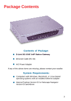
Package Contents Contents of Package: „ D-Link DG-104S VoIP Station Gateway „ Ethernet Cable (RJ-45) „ A/C Power Adapter If any of the above items are missing, please contact your reseller. System Requirements: „ Computers with Windows, Macintosh, or - D-Link DG-104S | Product Manual - Page 4
Introduction The D-Link DG-104S VoIP Station Gateway links traditional telephony networks to IP networks with conventional telephony devices such as analog phones or fax machines. The DG-104S includes four loop start Foreign Exchange Subscriber (FXS) interfaces with normal RJ-11 telephone connectors - D-Link DG-104S | Product Manual - Page 5
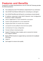
and Benefits Designed for versatility and performance, the DG-104S VoIP Gateway provides the following features: „ Four analog loop quality „ Command port for easy configuration „ Remote Software download/update „ Support IP sharing to allow multiple users to access the Internet via a single IP - D-Link DG-104S | Product Manual - Page 6
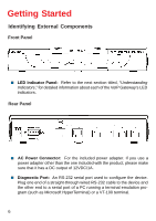
Components Front Panel „ LED Indicator Panel: Refer to the next section titled, "Understanding Indicators," for detailed information about each of the VoIP Gateway's LED indicators. Rear Panel „ AC Power Connector: For the included power adapter. If you use a power adapter other than the one - D-Link DG-104S | Product Manual - Page 7
10/100 dual-speed Ethernet port fitted with an RJ45 connector used to connect the VoIP gateway to a LAN device (hub, switch, PC, etc.). This port accepts Category connector. „ Do not place heavy objects on the DG-104S at any time. Placing the DG-104S in a well ventilated area is very important. Not - D-Link DG-104S | Product Manual - Page 8
Connecting the Network Cable Category 3, 4 or 5 UTP cable can be used to make the Ethernet connection to your router. Connecting the VoIP Gateway to a Computer The DG-104S requires a straight-through cable when connecting to a computer. Make sure that your IP address on your Ethernet card is in the - D-Link DG-104S | Product Manual - Page 9
your VoIP Gateway, take a few minutes to look over this section and familiarize yourself with the front panel LED indicators depicted below. Status „ Power: This LED is lit when the device is receiving power; otherwise, it is unlit. „ Status: This LED will flash quickly when the DG-104S is - D-Link DG-104S | Product Manual - Page 10
. „ Phone 1 to 4: Lights when standard phone port is in use. Note: If a powered-up device is connected to a port and the port's Link/Act status indicator is unlit, the most probable cause is a cabling or connection problem (for example, wrong cable type or bad contact) or a device malfunction. 10 - D-Link DG-104S | Product Manual - Page 11
or LAN Ethernet connections. In the discussion below, the computer running the browser is referred to as the management station. Configuring the VoIP Gateway Using a Console Setting up a Console First-time configuration can be carried out through a "console," that is, either (a) a VT100-type serial - D-Link DG-104S | Product Manual - Page 12
as a 1-bit stop interval) „ No Flow control „ Arrow keys enabled A typical console connection is illustrated below: Example of a Console Connection Configuring the VoIP Gateway Using Telnet Once you have set an IP address for your device, you can use a Telnet program (in a VT-100 compatible terminal - D-Link DG-104S | Product Manual - Page 13
: The command APPLY only applies for the current session. Use Save Changes from the Main Menu for permanent changes. First Time Connecting to the VoIP Gateway First make the console connection to the device and then power it on. If your terminal (or terminal emulation program) is properly configured - D-Link DG-104S | Product Manual - Page 14
„ Where the device receives its IP settings from. „ IP settings - IP Address, Subnet Mask, and Default Gateway „ Notify Entity - The address of the call agent „ Residential Gateway - A name for the VoIP gateway as it will be known by the call agent. All of these settings are found in the first menu - D-Link DG-104S | Product Manual - Page 15
the DNS function. „ BOOTP: Use the key to select the method that the VoIP gateway will use to obtain its IP settings once it is rebooted. Choices include: Manual: When Manual is selected, the VoIP gateway will obtain its IP settings from the fields located just below. BOOTP: When BOOTP is - D-Link DG-104S | Product Manual - Page 16
with a default IP address of 10.1.10.4. You must make sure that your computer is in the same subnet as the VoIP gateway. You can do this by changing the IP address of the computer using the screen shown below. Once this is done, run any browser on - D-Link DG-104S | Product Manual - Page 17
on the Login to the web-based management module button in the middle of the window. The following window will be displayed: Initially, the VoIP gateway does not have a Username or Password. To log in, simply click on the OK button. The following window will be displayed: Device Information window - D-Link DG-104S | Product Manual - Page 18
Configuration Configuring the VoIP Gateway To begin configuring the device, click on the Config IP folder on the left-hand side of the window (shown below). Next, click on Config Device IP Address. The following window will appear: Configure Device IP Address window 18 - D-Link DG-104S | Product Manual - Page 19
window are described below: Restart Settings „ Get IP From: Select the method the VoIP gateway will use to obtain its IP settings once it is rebooted. Choices include: Manual: When Manual is selected, the VoIP gateway will obtain its IP settings from the fields located just below. BOOTP: When BOOTP - D-Link DG-104S | Product Manual - Page 20
window are described below: „ Notify Entity: Enter the appropriate information for your call agent into this field. „ RGW Name: This is the residential gateway name your VoIP gateway will be known as by the call agent. It usually consists of the IP address or a normal name. „ DNS IP: Enter the IP - D-Link DG-104S | Product Manual - Page 21
Using the Boot Menu To access the Boot Menu, you must first make sure the console is connected to the Diagnostics port (an RS-232 port with a 9-socket D-shell connector and DCE-type wiring) and the appropriate cabling for the connection is being used. Please see the previous section, "Configuration - D-Link DG-104S | Product Manual - Page 22
the DNS function. „ BOOTP: Use the key to select the method that the VoIP gateway will use to obtain its IP settings once it is rebooted (restarted). Choices include: Manual: When Manual is selected, the VoIP gateway will obtain its IP settings from the fields located just below. BOOTP: When - D-Link DG-104S | Product Manual - Page 23
address: Enter an IP address for the VoIP gateway. „ Subnet mask: Enter a subnet mask for the VoIP gateway. „ Default gateway: Enter the IP address of the WAN be present after powering off or restarting the device. Make sure the Reset button on the rear panel of the device is in the down position - D-Link DG-104S | Product Manual - Page 24
the trap manager. „ IP: Enter the IP address of the trap manager. Device Information This screen displays various types of information about the DG-104S as well as allowing you to enter information pertaining to name, location, and how to reach the person responsible for maintaining the device. Use - D-Link DG-104S | Product Manual - Page 25
Number: This displays the serial number of this device. „ Boot PROM Version: This displays the version number of the device's startup code. „ Firmware Version: This displays the version number of the device's runtime code. „ System Country Code: This is a user-defined country code for this device - D-Link DG-104S | Product Manual - Page 26
changes in the fields above, press RESET DEVICE TO START UPDATE to initiate the This specifies downloading the image file through a WAN Link. „ TFTP Server Address: The IP address of This entry is used only if the Firmware Update is set to Enable. „ Firmware Update: Determines whether or not the - D-Link DG-104S | Product Manual - Page 27
Using the Boot Menu Update Firmware and Configuration Files „ File Name: The complete path and filename device, and they will be used every time it is powered on, reset, or rebooted. The only exception to this is a factory reset, which will clear all settings and restore them to their initial values, - D-Link DG-104S | Product Manual - Page 28
, use the arrow keys to highlight the fifth menu item on the Boot Menu, Factory Reset, and press . The Factory Reset screen will be displayed: Boot Menu-Factory Reset screen Restart System To perform a system reset, use the arrow keys to highlight the last menu item on the Boot Menu, Restart - D-Link DG-104S | Product Manual - Page 29
Using the Boot Menu Restart System Boot Menu-Restart System screen 29 - D-Link DG-104S | Product Manual - Page 30
The DG-104S VoIP gateway offers may vary with the screen shots (pictures) in this guide. Note: This Web-based Management Module does not accept manually through a console. See the Configuring the VoIP Gateway using a Web Browser section of the "Configuration" section for specific instructions - D-Link DG-104S | Product Manual - Page 31
, and xGCP Configuration), Firmware and Configuration Update, Save Changes, Factory Reset, and Restart System. Configure Device IP Address Configure Device IP Address window The items on this window are described below: Restart Settings „ Get IP From: Select the method the VoIP gateway will use to - D-Link DG-104S | Product Manual - Page 32
obtain its IP settings from a DCHP server located on your LAN. „ IP Address: Enter an IP address for the VoIP gateway. „ Subnet Mask: Enter a subnet mask for the VoIP gateway. „ Default Gateway: Enter the IP address of the WAN device (usually a router) you are using to make the WAN connection. PPPoE - D-Link DG-104S | Product Manual - Page 33
window are described below: „ Notify Entity: Enter the appropriate information for your call agent into this field. „ RGW Name: This is the residential gateway name your VoIP gateway will be known as by the call agent. It usually consists of the IP address or a normal name. „ DNS IP: Enter the IP - D-Link DG-104S | Product Manual - Page 34
MAC Address: This displays the MAC address of this device. „ Boot PROM Version: This displays the version number of the device's startup code. „ Firmware Version: This displays the version number of the device's runtime code. „ DSP Version: This displays the Digital Signal Processor version, if any - D-Link DG-104S | Product Manual - Page 35
Using Web-Based Management Telephony Configuration Telephony Configuration window Enter the desired information on the window above and then click Save. 35 - D-Link DG-104S | Product Manual - Page 36
Using Web-Based Management Dynamic IP Assignment Dynamic IP Assignment window Enter the desired information on the window above and then click Save. 36 - D-Link DG-104S | Product Manual - Page 37
Using Web-Based Management Static IP Assignment First Static IP Assignment window Click the pointer icon on the window above to access the second Static IP Assignment window: 37 - D-Link DG-104S | Product Manual - Page 38
Using Web-Based Management Static IP Assignment Second Static IP Assignment window Enter the desired information on the window above and then click Save. 38 - D-Link DG-104S | Product Manual - Page 39
Using Web-Based Management NAT Configuration NAT Configuration window After entering the desired information into the window above, enable or disable the NAT Function and then click Save. 39 - D-Link DG-104S | Product Manual - Page 40
Using Web-Based Management Local Server Configuration First Local Server Configuration window This window allows you to view the current local server configuration settings. Click the pointer icon on the window above to access the second Local Server Configuration window. 40 - D-Link DG-104S | Product Manual - Page 41
Using Web-Based Management Local Server Configuration Second Local Server Configuration window After completing the local server configuration settings on the window above, select enabled or disabled in the drop-down menu under State and then click Save. 41 - D-Link DG-104S | Product Manual - Page 42
Using Web-Based Management SNMP Trap Configuration SNMP Trap Configuration window The items on this window are described below: „ Trap Manager IP Address: The IP address of the trap receiving station. „ Community Name: A user-defined SNMP community name. „ SNMP AuthTrap: This allows you to enable or - D-Link DG-104S | Product Manual - Page 43
Using Web-Based Management Administration Management Administration Management window To add or change a User Account, fill in the appropriate information in the User Name, Old Password (if applicable), New Password, and Confirm New Password fields. Click on the Save button to keep the settings. 43 - D-Link DG-104S | Product Manual - Page 44
Using Web-Based Management Ethernet Statistics Ethernet Statistics window The items on this window are described below: „ Rx Packets: The total number of packets received by the device. „ Rx Bytes: The total number of bytes contained in packets received by the device. „ Rx Non Ucast Packets: The - D-Link DG-104S | Product Manual - Page 45
packets are generated by some proprietary software applications. „ Tx Packets: The total number of valid packets transmitted by the device since the last reset. „ Tx Bytes: The total number of bytes transmitted by the device. „ Tx Non Ucast Packets: The number of non-unicast packets sent. „ Tx - D-Link DG-104S | Product Manual - Page 46
Using Web-Based Management DSP Statistics DSP Statistics window This window displays a variety of DSP statistics. 46 - D-Link DG-104S | Product Manual - Page 47
Using Web-Based Management Tcid Configuration Tcid Configuration window This read-only window displays a variety of Tcid configuration settings. 47 - D-Link DG-104S | Product Manual - Page 48
Using Web-Based Management Coding Profile Coding Profile window This read-only window displays various Coding Profile settings. 48 - D-Link DG-104S | Product Manual - Page 49
Using Web-Based Management xGCP Configuration xGCP Configuration window This read-only window displays settings related to xGCP Configuration. 49 - D-Link DG-104S | Product Manual - Page 50
Update Mode: This specifies downloading the image file through a WAN Link or Lan Link. „ TFTP Server Address: The IP address of the TFTP server where the runtime or configuration file is located. This entry is used only if the Firmware Update is set to Enable. „ Last TFTP Server Address: This - D-Link DG-104S | Product Manual - Page 51
, they will become the default settings for the device, and they will be used every time it is powered on, reset or rebooted. The only exception to this is a factory reset, which will clear all settings and restore them to the initial values present when the device was purchased. Click on the - D-Link DG-104S | Product Manual - Page 52
the device's settings stored in NVRAM will be erased and restored to the values present when the device was purchased. Note: After performing the Factory Reset, make sure to redefine the IP settings for the device in the IP Configuration menu. Then perform a Restart System on the device. After these - D-Link DG-104S | Product Manual - Page 53
Using Web-Based Management Restart System Restart System window To perform a reboot of the device, which resets the system, click the Restart button. 53 - D-Link DG-104S | Product Manual - Page 54
Command Line Interface The DG-104S VoIP gateway offers a line-at-a-time prompt and response scheme to execute various configuration instructions. The interface displays a : nwdbg save changes nwdbg factory reset Definition: This command is used to set the DG-104S back to its default settings and - D-Link DG-104S | Product Manual - Page 55
Command Line Interface General Setup Commands nwdbg un Definition: This command sets the username if there is a username string, or shows the username/password if only nwdbg un is typed. Parameter(s): characters> - D-Link DG-104S | Product Manual - Page 56
mac Definition: This command sets the MAC address of the voice link, or shows the MAC address if only nwdbg mac is typed. Parameter(s): mode is used to set the device's IP address and upgrade the software. Manual: While the system is booting, the system uses a fixed IP address. - D-Link DG-104S | Product Manual - Page 57
the IP configuration. Parameter(s): Example: nwdbg mask 255.0.0.0 nwdbg gw Definition: This command sets the fixed GW address, which is used as the system's GW address if the software boot mode is Manual mode. If only nwdbg gw is typed, this command shows the IP - D-Link DG-104S | Product Manual - Page 58
link to either a WAN link or a LAN link. If only nwdbg tftp is typed, this command shows the download link. Parameter(s): - D-Link DG-104S | Product Manual - Page 59
Command Line Interface General Setup Commands nwdbg dns Definition: This command sets the Domain Name Server's IP address. If only nwdbg dns is typed, this command shows the DNS IP/STATE. Parameter(s): Example: nwdbg dns 10.1.1.5 nwdbg dns Definition: - D-Link DG-104S | Product Manual - Page 60
Command Line Interface General Setup Commands ping Definition: This command lets the user ping an IP address from the device. Parameter(s): - D-Link DG-104S | Product Manual - Page 61
Command Line Interface TFTP Client Setup Commands tftp srvip Definition: This command sets the IP address of the TFTP server. The image must be resident on that TFTP server. If the IP address is invalid, the message ERROR will be displayed. Example: ggdbg>tftp srvip 172.16.6.245 - D-Link DG-104S | Product Manual - Page 62
(MDI-X) „ IEEE 802.3 10BASE-T Ethernet compliance „ IEEE 802.3u 100BASE-TX Fast Ethernet compliant Quality of Service „ Voice service is prioritized over the data traffic. FAX Support „ V.21, V.27ter, V.29, V.17 Modulation/Demodulation. „ Fax Relay Protocols: T.38 Network Protocols: „ TCP/IP, UDP - D-Link DG-104S | Product Manual - Page 63
The built-in Trivial File Transfer Protocol provides firmware upgrade Security „ Password Authentication Protocol/Challenge Handshake and SNMP LEDs General „ Power „ Status Ethernet „ WAN: 10/100M, Link/Act „ LAN: 10/100M, Link/Act Dimensions „ 220(W) x 167.2(D) x 44.5(H) mm Number of Ports „ - D-Link DG-104S | Product Manual - Page 64
Technical Specifications Power Supply „ AC-to-DC power adapter (provided) „ DC Input: 12VDC/1A Operating Temperature „ -10 - 55 °C Storage Temperature „ -10 - 70 °C Humidity „ 5% - 95% non-condensing Safety „ CSA International (CSA 950, UL 1950, EN 60950, IEC 950) Emission (EMI) „ FCC Class B „ VCCI - D-Link DG-104S | Product Manual - Page 65
defective Hardware during the Warranty Period at no charge to the original owner or to refund at D-Link's sole discretion. Such repair or replacement will be rendered by D-Link at an Authorized D-Link Service Office. The replacement Hardware need not be new or have an identical make, model or part - D-Link DG-104S | Product Manual - Page 66
The product owner agrees to pay D-Link's reasonable handling and return shipping charges manual for the product, and normal maintenance; Damage that occurs in shipment, due to act of God, failures due to power surge, and cosmetic damage; Any hardware, software, firmware or other products or services - D-Link DG-104S | Product Manual - Page 67
such as translation, transformation, or adaptation without permission from D-Link Corporation/D-Link Systems, Inc., as stipulated by the United States Copyright Act and, if not installed and used in accordance with the instructions, may cause harmful interference to radio communication. However, - D-Link DG-104S | Product Manual - Page 68
Registration Register online your D-Link product at http://support.dlink.com/register/ 68 - D-Link DG-104S | Product Manual - Page 69
over the Telephone: (877) 453-5465 24 hours a day, seven days a week. D-Link Technical Support over the Internet: http://support.dlink.com email:[email protected] Tech Support for customers within Canada: D-Link Technical Support over the Telephone: (800) 361-5265 Monday to Friday 7:30am to 12:00am
-
 1
1 -
 2
2 -
 3
3 -
 4
4 -
 5
5 -
 6
6 -
 7
7 -
8
-
9
-
10
-
11
-
12
-
13
-
14
-
15
-
16
-
17
-
18
-
19
-
20
-
21
-
22
-
23
-
24
-
25
-
26
-
27
-
28
-
29
-
30
-
31
-
32
-
33
-
34
-
35
-
36
-
37
-
38
-
39
-
40
-
41
-
42
-
43
-
44
-
45
-
46
-
47
-
48
-
49
-
50
-
51
-
52
-
53
-
54
-
55
-
56
-
57
-
58
-
59
-
60
-
61
-
62
-
63
-
64
-
65
-
66
-
67
-
68
-
69
 |
 |

Manual
Building Networks for People
D-Link DG-104S
VoIP Station Gateway
Version 1.10