D-Link DGS-3620-28PC Hardware Installation Guide - Page 20
Mounting the Switch in a Standard 19\, Power On (AC Power), Alarm Connector
 |
View all D-Link DGS-3620-28PC manuals
Add to My Manuals
Save this manual to your list of manuals |
Page 20 highlights
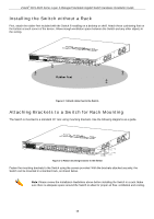
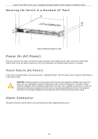
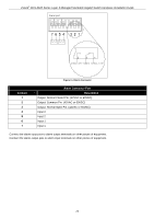
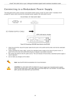
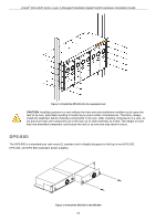
xStack® DGS-3620 Series Layer 3 Managed Stackable Gigabit Switch Hardware Installation Guide Mounting the Switch in a Standard 19" Rack Figure 2-3 Mount the Switch in a rack Power On (AC Power) Plug one end of the AC power cord into the power connector of the Switch and the other end into the local power source outlet. Once the system powered on, the LED's blink green to indicate that the system is resetting. Power Failure (AC Power) In the event of a power failure, just as a precaution, unplug the Switch. After the power returns, plug the switch back in to the power socket. CAUTION: Installing systems in a rack without the front and side stabilizers installed could cause the rack to tip over, potentially resulting in bodily injury under certain circumstances. Therefore, always install the stabilizers before installing components in the rack. After installing components in a rack, do not pull more than one component out of the rack on its slide assemblies at one time. The weight of more than one extended component could cause the rack to tip over and may result in injury. Alarm Connector The alarm connector can be used to use external devices when triggered events occur. 20
-
 1
1 -
2
-
3
-
4
-
5
-
6
-
7
-
8
-
9
-
10
-
11
-
12
-
13
-
14
-
 15
15 -
 16
16 -
 17
17 -
 18
18 -
 19
19 -
 20
20 -
 21
21 -
 22
22 -
 23
23 -
 24
24 -
 25
25 -
26
-
27
-
28
-
29
-
30
-
31
-
32
-
33
-
34
-
35
-
36
-
37
-
38
-
39
-
40
-
41
-
42
-
43
-
44
-
45
-
46
-
47
-
48
-
49
-
50
-
51
-
52
-
53
-
54
-
55
-
56
-
57
-
58
-
59
-
60
-
61
-
62
-
63
-
64
-
65
-
66
-
67
-
68
-
69
 |
 |
