D-Link DGS-3620-28PC Hardware Installation Guide - Page 27
Connecting the Switch, Switch to End Node, Switch to Switch
 |
View all D-Link DGS-3620-28PC manuals
Add to My Manuals
Save this manual to your list of manuals |
Page 27 highlights
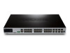
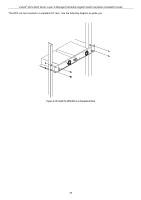
xStack® DGS-3620 Series Layer 3 Managed Stackable Gigabit Switch Hardware Installation Guide Chapter 3 Connecting the Switch Switch to End Node Switch to Switch Connect to a Network Backbone or Server Note: All high-performance N-Way Ethernet ports can support both MDI-II and MDI-X connections. Switch to End Node End nodes include PCs outfitted with a 10/100/1000 Mbps RJ-45 Ethernet Network Interface Card (NIC) and routers. An end node connects to the Switch via a twisted-pair UTP/STP cable. Connect the end node to any of the 1000BASE-T ports of the Switch. The Link/Act LEDs for each Ethernet port turns green or amber when the link is active. A blinking LED indicates packet activity on that port. Figure 3-1 Connect a DGS-3620 Series Switch to an end node Switch to Switch There is a great deal of flexibility on how connections are made using the appropriate cabling. • Connect a 10BASE-T switch port to the Switch via a twisted-pair Category 3, 4 or 5 UTP/STP cable. • Connect a 100BASE-TX switch port to the Switch via a twisted-pair Category 5 UTP/STP cable. • Connect 1000BASE-T switch port to the Switch via a twisted pair Category 5e UTP/STP cable. • Connect switch supporting a fiber-optic uplink to the Switch's SFP ports via fiber-optic cabling. 27
-
 1
1 -
2
-
3
-
4
-
5
-
6
-
7
-
8
-
9
-
10
-
11
-
12
-
13
-
14
-
15
-
16
-
17
-
18
-
19
-
20
-
21
-
 22
22 -
 23
23 -
 24
24 -
 25
25 -
 26
26 -
 27
27 -
 28
28 -
 29
29 -
 30
30 -
 31
31 -
 32
32 -
33
-
34
-
35
-
36
-
37
-
38
-
39
-
40
-
41
-
42
-
43
-
44
-
45
-
46
-
47
-
48
-
49
-
50
-
51
-
52
-
53
-
54
-
55
-
56
-
57
-
58
-
59
-
60
-
61
-
62
-
63
-
64
-
65
-
66
-
67
-
68
-
69
 |
 |
