D-Link DGS-3620-28PC Hardware Installation Guide - Page 23
Connecting to a Redundant Power Supply, Only the DGS-3620-28TC
 |
View all D-Link DGS-3620-28PC manuals
Add to My Manuals
Save this manual to your list of manuals |
Page 23 highlights
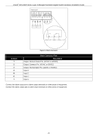
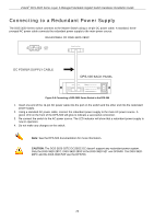
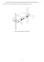
xStack® DGS-3620 Series Layer 3 Managed Stackable Gigabit Switch Hardware Installation Guide Connecting to a Redundant Power Supply The DGS 3620 Series switch connects to the Master Switch using a 14-pin DC power cable. A standard, threepronged AC power cable connects the redundant power supply to the main power source. Figure 2-6 Connecting a DGS-3620 Series Switch to the DPS-500 1. Insert one end of the 14-pin DC power cable into the port on the switch and the other end into the redundant power supply. 2. Using a standard AC power cable, connect the redundant power supply to the main AC power source. A green LED on the front of the DPS-500 will glow to indicate a successful connection. 3. Re-connect the switch to the AC power source. The LED indicator will show that a redundant power supply is now in operation. 4. Do not make any changes on the switch. Note: See the DPS-500 documentation for more information. CAUTION: The DGS-3620-28TC-DC/28SC-DC doesn't support any redundant power system. Only the DGS-3620-28TC, DGS-3620-28SC & the DGS-3620-52T use DPS500. The DGS-362028PC and the DGS-3620-52P use the DPS700. 23
-
 1
1 -
2
-
3
-
4
-
5
-
6
-
7
-
8
-
9
-
10
-
11
-
12
-
13
-
14
-
15
-
16
-
17
-
 18
18 -
 19
19 -
 20
20 -
 21
21 -
 22
22 -
 23
23 -
 24
24 -
 25
25 -
 26
26 -
 27
27 -
 28
28 -
29
-
30
-
31
-
32
-
33
-
34
-
35
-
36
-
37
-
38
-
39
-
40
-
41
-
42
-
43
-
44
-
45
-
46
-
47
-
48
-
49
-
50
-
51
-
52
-
53
-
54
-
55
-
56
-
57
-
58
-
59
-
60
-
61
-
62
-
63
-
64
-
65
-
66
-
67
-
68
-
69
 |
 |
