D-Link DSL-300I User Guide - Page 12
Front Panel, Rear Panel, DSL-300 ADSL Ethernet Modem User's Guide
 |
View all D-Link DSL-300I manuals
Add to My Manuals
Save this manual to your list of manuals |
Page 12 highlights
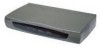
DSL-300 ADSL Ethernet Modem User's Guide Front Panel Place the Modem in a location that allows a view of the LED indicators shown in the front panel diagram below. Front Panel Rear Panel The rear panel of the Modem provides access to the power cord connection as well as the various communication port connections. Rear Panel 4
-
 1
1 -
2
-
3
-
4
-
5
-
6
-
 7
7 -
 8
8 -
 9
9 -
 10
10 -
 11
11 -
 12
12 -
 13
13 -
 14
14 -
 15
15 -
 16
16 -
 17
17 -
18
-
19
-
20
-
21
-
22
-
23
-
24
-
25
-
26
-
27
-
28
-
29
-
30
-
31
-
32
-
33
-
34
-
35
-
36
 |
 |

DSL-300 ADSL Ethernet Modem User’s Guide
4
Front Panel
Place the Modem in a location that allows a view of the LED indicators shown in
the front panel diagram below.
Front Panel
Rear Panel
The rear panel of the Modem provides access to the power cord connection as well
as the various communication port connections.
Rear Panel