D-Link DSN-1100-10 Hardware Reference Guide for DSN-1100-10 Valid for fir
D-Link DSN-1100-10 - xStack Storage Area Network Array Hard Drive Manual
 |
UPC - 790069321559
View all D-Link DSN-1100-10 manuals
Add to My Manuals
Save this manual to your list of manuals |
D-Link DSN-1100-10 manual content summary:
- D-Link DSN-1100-10 | Hardware Reference Guide for DSN-1100-10
Valid for fir - Page 1
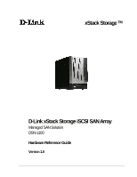
xStack Storage TM D-Link xStack Storage iSCSI SAN Array Managed SAN Solution DSN-1100 Hardware Reference Guide Version 1.0 - D-Link DSN-1100-10 | Hardware Reference Guide for DSN-1100-10
Valid for fir - Page 2
to change without notice. The only warranties for D-Link products and services are set forth in the express warranty statements accompanying such products and services. Nothing herein should be construed as constituting an additional warranty. D-Link shall not be liable for technical or editorial - D-Link DSN-1100-10 | Hardware Reference Guide for DSN-1100-10
Valid for fir - Page 3
Safety Information After completing the configuration of your DSN-1100 SAN array, please operate the unit with its front bezel door closed. This will help alleviate fire danger during normal SAN array operation. There is a danger of a new battery exploding if it is incorrectly installed. Replace the - D-Link DSN-1100-10 | Hardware Reference Guide for DSN-1100-10
Valid for fir - Page 4
Document Revision Level Revision Date Notes Version 1.0 November 10, 2008 iv - D-Link DSN-1100-10 | Hardware Reference Guide for DSN-1100-10
Valid for fir - Page 5
this document, the following documents are available from D-Link. xStack Storage Management Center Software User's Guide. This guide provides the information needed to configure and manage storage on the xStack Storage system using the xStack graphical user interface. DSN-1100 Hardware Reference - D-Link DSN-1100-10 | Hardware Reference Guide for DSN-1100-10
Valid for fir - Page 6
to Friday 8:00am - 5:00pm PST/PDT D-Link Technical Support over the Internet: http://support.dlink.com Tech Support for customers within Canada: D-Link Technical Support over the Telephone Please see our support site for current number: http://support.dlink.ca Monday to Friday 7:30am to 9:00pm - D-Link DSN-1100-10 | Hardware Reference Guide for DSN-1100-10
Valid for fir - Page 7
the DSN-1100 Storage System 21 3.3 Items Supplied by the User 21 3.4 Connecting to the iSCSI Data Ports 22 3.4.1 Connecting to the DSN-1100 Host Network Connection Ports 22 3.5 Connecting to the Management Port 22 3.6 Connecting the Power Cords 23 3.7 Powering-on the DSN-1100 Storage System - D-Link DSN-1100-10 | Hardware Reference Guide for DSN-1100-10
Valid for fir - Page 8
This Page Left Intentionally Blank viii Contents - D-Link DSN-1100-10 | Hardware Reference Guide for DSN-1100-10
Valid for fir - Page 9
D-Link Support Web site: support.dlink.com 1.1 Model The DSN-1100 storage system is presently available as a single model. Table 1-1. DSN-1100 Model Number Model DSN-1100-10 Host Network Interface Four 1GbE data ports Maximum Number of Internal SATA Drives 5 DSN-1100 Hardware Reference Guide - D-Link DSN-1100-10 | Hardware Reference Guide for DSN-1100-10
Valid for fir - Page 10
to preserve buffer cache contents if a power failure occurs. Contents are backed up for approximately 72 hours. 1.3 System Overview Figure 1-1 shows a typical DSN-1100 storage system configuration in a Storage Area Network (SAN). The SAN shown is an Ethernet network used solely for exchanging data - D-Link DSN-1100-10 | Hardware Reference Guide for DSN-1100-10
Valid for fir - Page 11
Chapter 2 DSN-1100 Layout This chapter describes the hardware components on the DSN-1100 storage system. The topics covered in this chapter are: Section 2.1, Front Panel Components Section 2.2, Inside Front Cover Section 2.3, Rear Panel Components DSN-1100 Hardware Reference Guide 11 - D-Link DSN-1100-10 | Hardware Reference Guide for DSN-1100-10
Valid for fir - Page 12
A lock on the bezel that protects access to the power switch and drives inside the unit. The hard drive power and drive activity/fault LEDs. (see Figure 2-2 and Table 2-2) Power LED Ready / Fault LED Figure 2-1. Front View of the DSN-1100 Storage System Lock Battery Status LED 12 Chapter - D-Link DSN-1100-10 | Hardware Reference Guide for DSN-1100-10
Valid for fir - Page 13
Ready/Fault Battery Status OFF Red Green Green Table 2-1. Front Panel LEDs Description ON = DSN-1100 is powered on. OFF = power is not being received. Array is powered off or performing its Power On Self Test. ON = a fault has occurred. ON = normal operation. ON (Illuminated steadily) = Good - D-Link DSN-1100-10 | Hardware Reference Guide for DSN-1100-10
Valid for fir - Page 14
Activity LEDs Table 2-2. Hard Drive LEDs (for each drive 00 through 04) Color Description Blue ON Green Blinking Red ON Drive is powered and operational. Data being transmitted or received from corresponding SATA drive. Drive has experienced a fault and is offline 14 Chapter 2 DSN-1100 Layout - D-Link DSN-1100-10 | Hardware Reference Guide for DSN-1100-10
Valid for fir - Page 15
2-3) Drive 00 Drive 01 Drive 02 Drive 03 Drive 04 Power Switch Figure 2-3. Front View with Cover Open Switch Power Table 2-3. Inside Front Cover Switch Description Applies power to the DSN-1100 storage system. Pressing this switch for longer than 3 seconds removes power from the DSN-1100 storage - D-Link DSN-1100-10 | Hardware Reference Guide for DSN-1100-10
Valid for fir - Page 16
the rear panel. Security lock slot - Receptacle fits the most common security lock. Four 1-Gigabit iSCSI RJ-45 Ports Reset Switch (small hole) Management Port Power Receptacle Diagnostic Port Security Lock Slot Figure 2-4. Back View of the DSN-1100 Storage System 16 Chapter 2 DSN-1100 Layout - D-Link DSN-1100-10 | Hardware Reference Guide for DSN-1100-10
Valid for fir - Page 17
DSN-1100 Rear Panel Switch Reset Table 2-4. Rear Panel Switch Description Resets the DSN-1100 storage system. Please use the tip of a pen or a paper clip to reset the system. Note: This reboots the system and does not reset the unit to initial factory settings. Table 2-5. Data Port Speed and Port - D-Link DSN-1100-10 | Hardware Reference Guide for DSN-1100-10
Valid for fir - Page 18
This Page Left Intentionally Blank 18 Chapter 2 DSN-1100 Layout - D-Link DSN-1100-10 | Hardware Reference Guide for DSN-1100-10
Valid for fir - Page 19
the DSN-1100 Storage System Section 3.3, Items Supplied by the User Section 3.4, Connecting to the iSCSI Data Ports Section 3.5, Connecting to the Management Port Section 3.6, Connecting the Power Cords Section 3.7, Powering-on the DSN-1100 Storage System DSN-1100 Hardware Reference Guide - D-Link DSN-1100-10 | Hardware Reference Guide for DSN-1100-10
Valid for fir - Page 20
equipment. The location should offer a power outlet within six feet (1.82 meters) of the DSN-1100 storage system. The location should allow for at least six inches (152.3 mm) of space around the DSN1100 storage system for ventilation. Do not place the DSN-1100 storage system next to, on top - D-Link DSN-1100-10 | Hardware Reference Guide for DSN-1100-10
Valid for fir - Page 21
. If you want to use the DSN-1100 storage system's Link Aggregation feature, the switch must support LAGs. An IP address for each DSN-1100 storage system host connection RJ-45 data port that will connect to your SAN. An Ethernet cable for each DSN-1100 storage system host connection RJ-45 data - D-Link DSN-1100-10 | Hardware Reference Guide for DSN-1100-10
Valid for fir - Page 22
other end of the cable into the DSN-1100 storage system Mgmt 10/100 port. This port is located to the right of the diagnostic port on the back panel. Do not connect one NIC to the management and host network connection ports. Connect one NIC to the management port and connect another NIC in the same - D-Link DSN-1100-10 | Hardware Reference Guide for DSN-1100-10
Valid for fir - Page 23
the diagnostic port. After the DSN-1100 storage system powers-on for the first time, it automatically loads the factory-default configuration settings. If necessary, you can use the xStack Storage Management Center to change these settings to suit your requirements. For a description of the array - D-Link DSN-1100-10 | Hardware Reference Guide for DSN-1100-10
Valid for fir - Page 24
This Page Left Intentionally Blank 24 Chapter 3 Installing the DSN-1100 Storage System - D-Link DSN-1100-10 | Hardware Reference Guide for DSN-1100-10
Valid for fir - Page 25
or upgraded include: Battery Pack System and buffer memory SATA drives Fans Power supply A.1 Removing the Cover To remove the cover, use the following procedure. 1. Power down the DSN-1100 storage system and remove the power cord from the back panel. 2. Attach an ESD-preventive wrist strap - D-Link DSN-1100-10 | Hardware Reference Guide for DSN-1100-10
Valid for fir - Page 26
Screw Screw Screw Screw Screw Figure A-1. Removing the Cover Screw Slide Cover to Rear and Lift Up Figure A-2. Slide the Cover Back and Remove 26 Appendix A Replacing and Upgrading FRUs - D-Link DSN-1100-10 | Hardware Reference Guide for DSN-1100-10
Valid for fir - Page 27
xStack Storage Array accommodates a shrink-wrapped battery pack. Because write-back caching is always enabled, we recommend you have a battery to back up the buffer cache contents. The battery pack connects to the DSN-1100 Battery Pack Connector (J11) Location DSN-1100 Hardware Reference Guide 27 - D-Link DSN-1100-10 | Hardware Reference Guide for DSN-1100-10
Valid for fir - Page 28
To install a battery in your xStack Storage SAN Array, follow these steps: 1. Hold the battery as shown to align the fastener strips. Make sure the battery cable and connector is located nearest to the - D-Link DSN-1100-10 | Hardware Reference Guide for DSN-1100-10
Valid for fir - Page 29
the battery plug with connector J11 as shown in Figure A-7 and insert it fully into the socket. Figure A-7 Align the Battery Plug with Connector J11 DSN-1100 Hardware Reference Guide 29 - D-Link DSN-1100-10 | Hardware Reference Guide for DSN-1100-10
Valid for fir - Page 30
5. The connector locked firmly into connector J11 as shown in Figure A-8. Figure A-8 Battery Plug Locked in Place 6. The installed battery is shown in Figure A-9. Figure A-9 The Installed Battery 30 Appendix A Replacing and Upgrading FRUs - D-Link DSN-1100-10 | Hardware Reference Guide for DSN-1100-10
Valid for fir - Page 31
of your SAN array. Please visit the support.dlink.com website for tested memory modules. Table A-2 shows the possible memory configurations for your xStack Storage controller. System Memory Rear of Chassis Figure A-10. Looking down at the controller board. Buffer (Cache) Memory DSN-1100 Hardware - D-Link DSN-1100-10 | Hardware Reference Guide for DSN-1100-10
Valid for fir - Page 32
Figure A-11 Buffer(Cache) Memory DIMM Socket Figure A-12 System Memory DIMM Socket 32 Appendix A Replacing and Upgrading FRUs - D-Link DSN-1100-10 | Hardware Reference Guide for DSN-1100-10
Valid for fir - Page 33
xStack Storage Array DIMM power cord from the back panel. 2. Attach an ESD-preventive wrist strap. 3. Open the enclosure to access the DSN-1100 storage system Controller (see section A.1). 4. Remove all five drive trays from the system and look down at the controller board as shown in figure A-10 - D-Link DSN-1100-10 | Hardware Reference Guide for DSN-1100-10
Valid for fir - Page 34
A-14. Inserting a DIMM 9. Snap the latches into place. Do not use excessive force, because the socket might break. 10. Replace the cover (see section A.1). 11. Power on the DSN-1100 storage system. If error messages relating to memory are displayed, remove the DIMM and reinstall it, making sure to - D-Link DSN-1100-10 | Hardware Reference Guide for DSN-1100-10
Valid for fir - Page 35
can be part of a volume that may or may not be redundant. Before removing a drive from an operating xStack Storage Array, make sure it is the correct one. A.3.1 Drive and Tray Removal A drive/tray assembly can be removed by pressing upwards on the green latch found on the tray and removing it with - D-Link DSN-1100-10 | Hardware Reference Guide for DSN-1100-10
Valid for fir - Page 36
Follow these steps to install a hard drive in a drive tray. 1. If there is one, remove the plastic air dam from the tray by squeezing the two levers together and lifting the piece out of - D-Link DSN-1100-10 | Hardware Reference Guide for DSN-1100-10
Valid for fir - Page 37
hard drive in tray as shown in Figure A-19. Figure A-19 Place Hard Drive in Tray 4. Align the mounting holes and insert four mounting screws to hold the drive securely in the drive tray as shown in Figure A-. Figure A-20 Secure the Hard Drive in the Drive Tray DSN-1100 Hardware Reference Guide 37 - D-Link DSN-1100-10 | Hardware Reference Guide for DSN-1100-10
Valid for fir - Page 38
is ready for installation. Proceed to A.3.3. A.3.3 Drive and Tray Installation A drive/tray assembly can be installed by inserting the drive/tray assembly into the open drive bay as shown in Figure A-21. Push the tray at the point indicated in Step 2 of Figure A-22 and push until it is seated firmly - D-Link DSN-1100-10 | Hardware Reference Guide for DSN-1100-10
Valid for fir - Page 39
Figure A-22 Press Here Until You See the Lever Move Inwards Figure A-23 Press Lever Inwards Until it Locks DSN-1100 Hardware Reference Guide 39 - D-Link DSN-1100-10 | Hardware Reference Guide for DSN-1100-10
Valid for fir - Page 40
A.4 Replacing a Power Supply The DSN-1100 xStack Storage Array contains one user replaceable power supply. It can be replaced as follows. To replace the power supply, use the following procedure. 1. Power down the DSN-1100 storage system and remove the power cord from the back panel. 2. Attach an - D-Link DSN-1100-10 | Hardware Reference Guide for DSN-1100-10
Valid for fir - Page 41
the bottom of the chassis. Screw Screw Figure A-25 Remove These Two Screws on the Bottom of the Chassis 6. Open the clip which holds the power supply wiring harness in place as shown in Figure A-26. Figure A-26 Open the Power Supply Harness Retention Clip DSN-1100 Hardware Reference Guide 41 - D-Link DSN-1100-10 | Hardware Reference Guide for DSN-1100-10
Valid for fir - Page 42
Supply Harness Connector 8. Carefully slide the power supply out of the chassis as shown in Figure A-28. NOTE: Be sure not to damage the insulation on the wiring harness Figure A-28 Remove the Power Supply Harness Connector 9. To install a power supply, please reverse these steps. 42 Appendix
-
 1
1 -
 2
2 -
 3
3 -
 4
4 -
 5
5 -
 6
6 -
 7
7 -
8
-
9
-
10
-
11
-
12
-
13
-
14
-
15
-
16
-
17
-
18
-
19
-
20
-
21
-
22
-
23
-
24
-
25
-
26
-
27
-
28
-
29
-
30
-
31
-
32
-
33
-
34
-
35
-
36
-
37
-
38
-
39
-
40
-
41
-
42
 |
 |

xStack Storage
TM
D-Link xStack Storage iSCSI SAN Array
Managed SAN Solution
DSN-1100
Hardware Reference Guide
Version 1.0