D-Link DSN-1100-10 Hardware Reference Guide for DSN-1100-10 Valid for fir - Page 38
A.3.3, Drive and Tray Installation
 |
UPC - 790069321559
View all D-Link DSN-1100-10 manuals
Add to My Manuals
Save this manual to your list of manuals |
Page 38 highlights
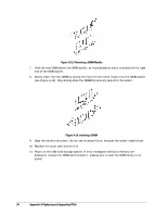
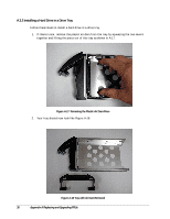
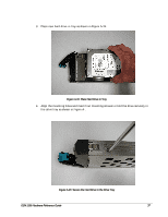
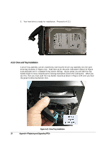
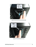
5. Your hard drive is ready for installation. Proceed to A.3.3. A.3.3 Drive and Tray Installation A drive/tray assembly can be installed by inserting the drive/tray assembly into the open drive bay as shown in Figure A-21. Push the tray at the point indicated in Step 2 of Figure A-22 and push until it is seated firmly within the bay. As you press, you will see the tray handle begin to move inwards as the locking mechanism enters the locking slot. When you see this, then you must push the tray handle inwards as shown in Figure A-23 until you hear the green locking mechanism click. Figure A-21 Drive/Tray Installation 38 Appendix A Replacing and Upgrading FRUs
-
 1
1 -
2
-
3
-
4
-
5
-
6
-
7
-
8
-
9
-
10
-
11
-
12
-
13
-
14
-
15
-
16
-
17
-
18
-
19
-
20
-
21
-
22
-
23
-
24
-
25
-
26
-
27
-
28
-
29
-
30
-
31
-
32
-
 33
33 -
 34
34 -
 35
35 -
 36
36 -
 37
37 -
 38
38 -
 39
39 -
 40
40 -
 41
41 -
 42
42
 |
 |

38
Appendix A Replacing and Upgrading FRUs
5.
Your hard drive is ready for installation.
Proceed to A.3.3.
A.3.3
Drive and Tray Installation
A drive/tray assembly can be installed by inserting the drive/tray assembly into the open
drive bay as shown in Figure A-21.
Push the tray at the point indicated in Step 2 of Figure
A-22 and push until it is seated firmly within the bay.
As you press, you will see the tray
handle begin to move inwards as the locking mechanism enters the locking slot.
When you
see this, then you must push the tray handle inwards as shown in Figure A-23 until you hear
the green locking mechanism click.
Figure A-21
Drive/Tray Installation