D-Link DSN-1100-10 Hardware Reference Guide for DSN-1100-10 Valid for fir - Page 12
Front Panel Components
 |
UPC - 790069321559
View all D-Link DSN-1100-10 manuals
Add to My Manuals
Save this manual to your list of manuals |
Page 12 highlights
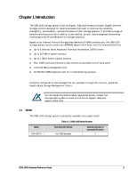
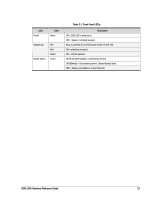
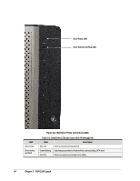
2.1 Front Panel Components The front of the DSN-1100 storage system has the following components: Power LED - shows the DSN-1100 power on status. (see Figure 2-1 and Table 2-1) Ready/Fault LED - shows whether the DSN-1100 is ready for operation or encountered a fault condition. (see Figure 2-1 and Table 2-1) Battery Status LED - shows the state of the internal cache memory battery. (see Figure 2-1 and Table 2-1) A lock on the bezel that protects access to the power switch and drives inside the unit. The hard drive power and drive activity/fault LEDs. (see Figure 2-2 and Table 2-2) Power LED Ready / Fault LED Figure 2-1. Front View of the DSN-1100 Storage System Lock Battery Status LED 12 Chapter 2 DSN-1100 Layout
-
 1
1 -
2
-
3
-
4
-
5
-
6
-
 7
7 -
 8
8 -
 9
9 -
 10
10 -
 11
11 -
 12
12 -
 13
13 -
 14
14 -
 15
15 -
 16
16 -
 17
17 -
18
-
19
-
20
-
21
-
22
-
23
-
24
-
25
-
26
-
27
-
28
-
29
-
30
-
31
-
32
-
33
-
34
-
35
-
36
-
37
-
38
-
39
-
40
-
41
-
42
 |
 |

12
Chapter 2 DSN-1100 Layout
2.1
Front Panel Components
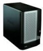
The front of the DSN-1100 storage system has the following components:
Power LED – shows the DSN-1100 power on status. (see Figure 2-1 and Table 2-1)
Ready/Fault LED – shows whether the DSN-1100 is ready for operation or encountered a
fault condition. (see Figure 2-1 and Table 2-1)
Battery Status LED – shows the state of the internal cache memory battery. (see Figure
2-1 and Table 2-1)
A lock on the bezel that protects access to the power switch and drives inside the unit.
The hard drive power and drive activity/fault LEDs.
(see Figure 2-2 and Table 2-2)
Figure 2-1. Front View of the DSN-1100 Storage System
Power LED
Battery
Status LED
Lock
Ready / Fault LED