Dell Force10 S4810P Quick Start Guide
Dell Force10 S4810P Manual
 |
View all Dell Force10 S4810P manuals
Add to My Manuals
Save this manual to your list of manuals |
Dell Force10 S4810P manual content summary:
- Dell Force10 S4810P | Quick Start Guide - Page 1
Dell Force10 S4810 System Quick Start Guide Regulatory Model: S4810P - Dell Force10 S4810P | Quick Start Guide - Page 2
- Dell Force10 S4810P | Quick Start Guide - Page 3
Dell Force10 S4810 System Quick Start Guide Regulatory Model: S4810P - Dell Force10 S4810P | Quick Start Guide - Page 4
instructions are not followed. WARNING: A WARNING indicates a potential for property damage, personal injury, or death. If you purchased a Dell © 2011 Dell Inc. All Dell Inc. is strictly forbidden. Trademarks used in this text: Dell™, the DELL logo, Dell Dell Inc. disclaims any proprietary interest in trademarks - Dell Force10 S4810P | Quick Start Guide - Page 5
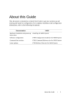
, refer to the following documents: Documentation S4810 Hardware installation and power-up Installing the S4810 System instructions Software configuration FTOS Configuration Guide for the S4810 System Command line interface FTOS Command Reference for the S4810 System Latest updates FTOS - Dell Force10 S4810P | Quick Start Guide - Page 6
2 About this Guide - Dell Force10 S4810P | Quick Start Guide - Page 7
1 Installing the Hardware This guide assumes all site preparation has been performed before installing the chassis. Installing the S4810 Chassis in a Rack or Cabinet To install the S4810 system, Dell Force10 recommends that you complete the installation procedures in the order presented below. - Dell Force10 S4810P | Quick Start Guide - Page 8
Power Supply View from chassis I/O side Connect to Rack/Cabinet (ears) Screws View of chassis PSU side Screws Connect to Install chassis into 2-post rack or cabinet Step Task 1 Dell Force10 recommends that one person hold the S4810 . Dell Force10 recommends a 6AWG one-hole lug, #10 hole - Dell Force10 S4810P | Quick Start Guide - Page 9
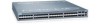
end of the ground cable to a suitable ground point. The rack installation ears are not a suitable grounding point. Install the SFP+ QSFP+ Optics The S4810 has 48 SFP+ optical ports and 4 QSFP+ optical ports. For supported optics, refer to http://www.force10networks.com/products/specifications.asp - Dell Force10 S4810P | Quick Start Guide - Page 10
a 40G port into 4x10G port is supported only on a standalone unit. • Split ports cannot be used as stack-link to stack an S4810. • Split ports S4810 unit cannot be a part of any stacked system. • The unit number with the split ports must be the default (stack-unit 0). This can be verified using - Dell Force10 S4810P | Quick Start Guide - Page 11
is at the top of the PSU when the unit is correctly installed. Connect the plug to each AC power connector, making sure that the power cord is secure. As soon as the cable is connected between the S4810 and the power source, the chassis is powered-up; there is no on/off switch. DC Power Connect the - Dell Force10 S4810P | Quick Start Guide - Page 12
S4810 supports two airflow direction options. Only a single direction can be used in a chassis; do not mix fan flow types in a chassis. The system will shutdown in 1 minute, if the airflow directions are mismatched. • Normal is airflow from I/O panel to power supply. • Reversed is airflow from power - Dell Force10 S4810P | Quick Start Guide - Page 13
Power Consumption Specifications 230 Watts (nominal) 270 Watts (maximum) Environmental Parameters Parameter Temperature Maximum altitude Relative humidity Shock Specifications 32° to 104°F (0° to 40°C) -40° to 158°F (-20° to 70°C) No performance degradation to 10,000 feet (3,048 meters) 10 - Dell Force10 S4810P | Quick Start Guide - Page 14
. The S4810 supports AC power supplies with two air-flow directions (Normal and Reversed). Two power supplies are required for full redundancy, but the system will operate with a single power supply. NOTE: If using a single PSU, you must install a blank plate in the other PSU slot. Dell Force10 - Dell Force10 S4810P | Quick Start Guide - Page 15
bay. 3 Tighten the securing screw on the side of the PSU. 4 Attach power cables. 5 The system powers up as soon as the cables are connected between the power supply and the power source. DC Power Supply PSU0 Fan Modules Cable Connector PSU1 Grab Handle Installing the Hardware 11 - Dell Force10 S4810P | Quick Start Guide - Page 16
12 Installing the Hardware - Dell Force10 S4810P | Quick Start Guide - Page 17
already installed on your PC. The RS-232 console port is labeled on the S4810 chassis. It is in the upper righthand side, as you face the I/O RJ-45 copper cable into the console port. Use a rollover cable to connect the S4810 console port to a terminal server. 2 Connect the other end of the cable - Dell Force10 S4810P | Quick Start Guide - Page 18
default host name, which is Force10). You must configure the system using the CLI. Configure Layer 2 (Data Link) Mode Use the switchport command in INTERFACE mode to enable Layer 2 data transmissions through an individual interface. The user cannot configure switching or Layer 2 protocols such as - Dell Force10 S4810P | Quick Start Guide - Page 19
2 Place the interface in switchport Layer 2 (switching) mode. Command Mode INTERFACE To view the interfaces in Layer 2 mode, use the show interfaces switchport command in the EXEC mode. Configure a Host Name The host name appears in the prompt. The default host name is force10. • Host names - Dell Force10 S4810P | Quick Start Guide - Page 20
ip address ip-address/mask to the interface. 3 Enable the interface. no shutdown Command Mode CONFIGURATION INTERFACE INTERFACE Configure a Management Route Define a path from the system to the network from which you are accessing the system remotely. Management routes are separate from IP routes - Dell Force10 S4810P | Quick Start Guide - Page 21
method. Dell Force10 recommends using the enable secret password. Task Command Syntax Create a password to enable [password | secret] [level level] access EXEC [encryption-type] password Privilege mode. Command Mode CONFIGURATION Create a Port-based VLAN The Default VLAN as VLAN 1 is part of - Dell Force10 S4810P | Quick Start Guide - Page 22
: Step Task Command Syntax 1 Access the interface vlan vlan-id INTERFACE VLAN mode of the VLAN to which you want to assign the interface. 2 Enable an interface to tagged interface include the IEEE 802.1Q tag header. Command Mode CONFIGURATION INTERFACE Use the untagged command to move - Dell Force10 S4810P | Quick Start Guide - Page 23
, by default, is VLAN 1. To assign another VLAN ID to the Default VLAN, use the default vlan-id vlan-id command. Task Command Syntax Configure an IP address ip address ip-address mask and mask on the interface. [secondary] Command Mode INTERFACE Connecting the S4810 to the Network Once you have - Dell Force10 S4810P | Quick Start Guide - Page 24
20 Installing the Software - Dell Force10 S4810P | Quick Start Guide - Page 25
- Dell Force10 S4810P | Quick Start Guide - Page 26
Printed in the U.S.A. www.dell.com | support.dell.com
-
 1
1 -
 2
2 -
 3
3 -
 4
4 -
 5
5 -
 6
6 -
 7
7 -
8
-
9
-
10
-
11
-
12
-
13
-
14
-
15
-
16
-
17
-
18
-
19
-
20
-
21
-
22
-
23
-
24
-
25
-
26
 |
 |
Dell Force10
S4810 System
Quick Start Guide
Regulatory Model: S4810P