Dell Inspiron 14 5420 Service Manual
Dell Inspiron 14 5420 Manual
 |
View all Dell Inspiron 14 5420 manuals
Add to My Manuals
Save this manual to your list of manuals |
Dell Inspiron 14 5420 manual content summary:
- Dell Inspiron 14 5420 | Service Manual - Page 1
Inspiron 14 5420 Service Manual Regulatory Model: P157G Regulatory Type: P157G001/P157G002 February 2022 Rev. A00 - Dell Inspiron 14 5420 | Service Manual - Page 2
of data and tells you how to avoid the problem. WARNING: A WARNING indicates a potential for property damage, personal injury, or death. © 2022 Dell Inc. or its subsidiaries. All rights reserved. Dell, EMC, and other trademarks are trademarks of Dell Inc. or its subsidiaries. Other trademarks may be - Dell Inspiron 14 5420 | Service Manual - Page 3
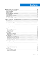
-ESD protection...7 ESD field service kit ...8 Transporting sensitive components...9 Exiting Service Mode...9 After working inside your computer...9 Chapter 2: Removing and installing components 10 Recommended tools...10 Screw list...10 Major components of Inspiron 14 5420...11 Base cover...13 - Dell Inspiron 14 5420 | Service Manual - Page 4
Installing the palm-rest and keyboard assembly 58 Chapter 3: Drivers and downloads 60 Chapter 4: System setup...61 Entering BIOS setup 69 Chapter 5: Troubleshooting...70 Handling swollen Lithium-ion batteries...70 Locate the Service Tag or Express Service Code of your Dell computer 70 System- - Dell Inspiron 14 5420 | Service Manual - Page 5
SupportAssist | On-board Diagnostics...72 Recovering the operating system...72 WiFi power cycle...72 Drain residual flea power (perform hard reset)...73 Chapter 6: Getting help and contacting Dell 74 Contents 5 - Dell Inspiron 14 5420 | Service Manual - Page 6
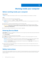
and press the power button for 3 seconds or until the Dell logo appears on the screen. 3. Press any key to continue any key to continue the Service Mode procedure. NOTE: The Service Mode procedure automatically skips the following the system board. Safety instructions Use the following safety - Dell Inspiron 14 5420 | Service Manual - Page 7
troubleshooting and repairs as authorized or directed by the Dell technical assistance team. Damage due to servicing that is not authorized by Dell is not covered by your warranty. See the safety instructions may not be obvious, such as intermittent problems or a shortened product life span. As the - Dell Inspiron 14 5420 | Service Manual - Page 8
for safe transport. ESD protection summary It is recommended that all field service technicians use the traditional wired ESD grounding wrist strap and protective anti-static mat at all times when servicing Dell products. In addition, it is critical that technicians keep sensitive parts separate - Dell Inspiron 14 5420 | Service Manual - Page 9
or parts to be returned to Dell, it is critical to place and point your toes out. 2. Tighten stomach muscles. Abdominal muscles support your spine when you lift, offsetting the force of the load. reverse to set the load down. Exiting Service Mode Service Mode allows users to immediately cut off - Dell Inspiron 14 5420 | Service Manual - Page 10
2 Removing and installing components NOTE: The images in this document may differ from your computer depending on the configuration you ordered. Recommended tools The procedures in this document may require the following tools: ● Phillips screwdriver #0 ● Phillips screwdriver #1 ● Plastic scribe - Dell Inspiron 14 5420 | Service Manual - Page 11
M2.5x4 assembly I/O board System board Palm-rest and keyboard assembly Palm-rest and keyboard assembly M2x3 M2x1.8 Quantity 3 1 2 4 1 2 Major components of Inspiron 14 5420 The following image shows the major components of Inspiron 14 5420. Screw image Removing and installing components 11 - Dell Inspiron 14 5420 | Service Manual - Page 12
1. Base cover 2. USB-C port bracket 3. System board 4. Coin-cell battery 5. Left speaker 6. Heat sink 7. Memory 8. Palm-rest and keyboard assembly 9. Display assembly 10. Touchpad 11. Touchpad bracket 12. I/O board 12 Removing and installing components - Dell Inspiron 14 5420 | Service Manual - Page 13
13. Power-button with optional fingerprint-reader 14. Wireless-card bracket 15. Wireless card 16. Battery 17. Battery cable 18. Fan 19. M.2 solid-state drive (M.2 2280 solid-state drive shown) 20. Power-adapter port NOTE: Dell provides a list of components and their part numbers for the original - Dell Inspiron 14 5420 | Service Manual - Page 14
14 Removing and installing components - Dell Inspiron 14 5420 | Service Manual - Page 15
Steps 1. Remove the five screws (M2x4) that secure the base cover to the palm-rest assembly. 2. Loosen the two captive screws. 3. Using a plastic scribe, pry the base cover from the bottom left and continue to work on the sides to open the base cover. 4. Lift and slide the base cover off the palm- - Dell Inspiron 14 5420 | Service Manual - Page 16
Installing the base cover Prerequisites If you are replacing a component, remove the existing component before performing the installation process. About this task The following image(s) indicate the location of the base cover and provides a visual representation of the installation procedure. 16 - Dell Inspiron 14 5420 | Service Manual - Page 17
Steps 1. Connect the battery cable to the system board. 2. Place and snap the base cover into place on the palm-rest assembly. 3. Tighten the two captive screws on the base cover. 4. Replace the five screws (M2x4) that secure the base cover to the palm-rest assembly. Next steps 1. Follow the - Dell Inspiron 14 5420 | Service Manual - Page 18
secures the battery cable to the battery. 2. Disconnect the battery cable from the system board. 3. Remove the battery cable from the routing guides on the battery. 4. Disconnect the battery cable from the battery. 5. Lift the battery cable off the battery. Installing the battery cable Prerequisites - Dell Inspiron 14 5420 | Service Manual - Page 19
to the battery. 2. Route the battery cable through the routing guides on the battery. 3. Connect the battery cable to the system any kind to pry on or against the battery. ● Ensure any screws during the servicing of this product are not lost or misplaced, to prevent accidental puncture or damage to - Dell Inspiron 14 5420 | Service Manual - Page 20
or crushing a lithium-ion battery can be dangerous. In such an instance, contact Dell technical support for assistance. See www.dell.com/contactdell. ● Always purchase genuine batteries from www.dell.com or authorized Dell partners and resellers. ● Swollen batteries should not be used and should be - Dell Inspiron 14 5420 | Service Manual - Page 21
inside your computer. Coin-cell battery Removing the coin-cell battery Prerequisites 1. Follow the procedure in Before working inside your computer. 2. Enter Service Mode. 3. Remove the base cover. About this task NOTE: Before removing the base cover, ensure that there is no SD card installed - Dell Inspiron 14 5420 | Service Manual - Page 22
Steps 1. Disconnect the coin-cell battery from the I/O board. 2. Peel and lift the coin-cell battery from the palm-rest and keyboard assembly. Installing the coin-cell battery Prerequisites If you are replacing a component, remove the existing component before performing the installation process. - Dell Inspiron 14 5420 | Service Manual - Page 23
the battery. Next steps 1. Install the base cover. 2. Exit Service Mode. 3. Follow the procedure in After working inside your computer. Solid drive installed on your computer depends on the configuration ordered. The M.2 slot supports one of the following solid-state drives: ● M.2 2230 solid-state - Dell Inspiron 14 5420 | Service Manual - Page 24
(shipped with the computer) with an M.2 2230 solid-state drive, a mounting bracket for the M.2 2230 solid-state drive is required. Please contact Dell support to purchase the mounting bracket for the M.2 2230 solid-state drive. The following image(s) indicate the location of the M.2 2230 solid-state - Dell Inspiron 14 5420 | Service Manual - Page 25
(shipped with the computer) with an M.2 2230 solid-state drive, a mounting bracket for the M.2 2230 solid-state drive is required. Please contact Dell support to purchase the mounting bracket for the M.2 2230 solid-state drive. The following image(s) indicate the location of the M.2 2230 solid-state - Dell Inspiron 14 5420 | Service Manual - Page 26
the screw (M2x3) that secures the M.2 2230 solid-state drive bracket to the system board. Next steps 1. Install the base cover. 2. Exit Service Mode. 3. Follow the procedure in After working inside your computer. Removing the M.2 2280 solid-state drive Prerequisites 1. Follow the procedure in Before - Dell Inspiron 14 5420 | Service Manual - Page 27
(shipped with the computer) with an M.2 2230 solid-state drive, a mounting bracket for the M.2 2230 solid-state drive is required. Please contact Dell support to purchase the mounting bracket for the M.2 2230 solid-state drive. The following image(s) indicate the location of the M.2 2280 solid-state - Dell Inspiron 14 5420 | Service Manual - Page 28
bracket for the M.2 2230 solid-state drive is required. Please contact Dell support to purchase the mounting bracket for the M.2 2230 solid-state drive. steps 1. Install the base cover. 2. Exit Service Mode. 3. Follow the procedure in After working inside your computer. 28 Removing - Dell Inspiron 14 5420 | Service Manual - Page 29
Memory module Removing the memory module Prerequisites 1. Follow the procedure in Before working inside your computer. 2. Enter Service Mode. 3. Remove the base cover. About this task The following image(s) indicate the location of the memory module and provides a visual representation of the - Dell Inspiron 14 5420 | Service Manual - Page 30
board. 4. Press down on the memory module till the securing clips click, locking the memory module in place. Next steps 1. Install the base cover. 2. Exit Service Mode. 30 Removing and installing components - Dell Inspiron 14 5420 | Service Manual - Page 31
inside your computer. Wireless card Removing the wireless card Prerequisites 1. Follow the procedure in Before working inside your computer. 2. Enter Service Mode. 3. Remove the base cover. About this task The following image(s) indicate the location of the wireless card and provides a visual - Dell Inspiron 14 5420 | Service Manual - Page 32
Installing the wireless card Prerequisites If you are replacing a component, remove the existing component before performing the installation process. About this task The following image(s) indicate the location of the wireless card and provides a visual representation of the installation procedure. - Dell Inspiron 14 5420 | Service Manual - Page 33
Follow the procedure in Before working inside your computer. 2. Enter Service Mode. 3. Remove the base cover. 4. Remove the display assembly to the system board. 5. Remove the power-adapter port cable from the routing guide on the palm-rest and keyboard assembly. 6. Lift the power-adapter port, along - Dell Inspiron 14 5420 | Service Manual - Page 34
rest and keyboard assembly. 2. Route the power-adapter port cable through the routing guide on the palm-rest and keyboard assembly. 3. Adhere the tape that secures the . 2. Install the base cover. 3. Exit Service Mode. 4. Follow the procedure in After working inside your computer. - Dell Inspiron 14 5420 | Service Manual - Page 35
Display assembly Removing the display assembly Prerequisites 1. Follow the procedure in Before working inside your computer. 2. Enter Service Mode. 3. Remove the base cover. About this task The following image(s) indicate the location of the display assembly and provides a visual representation of - Dell Inspiron 14 5420 | Service Manual - Page 36
Steps 1. Peel the tape that secures the display-cable connector latch to the system board. 2. Lift the latch and disconnect the display-cable from the connector on the system board. 3. Remove the two screws (M2.5x4) that secure the right display hinge to the system board. 4. Pry open the right - Dell Inspiron 14 5420 | Service Manual - Page 37
5. Remove the two screws (M2.5x4) that secure the left display hinge to the I/O board. 6. Pry open the left display hinge at an angle of 90 degrees. 7. Gently lift the palm-rest and keyboard assembly off the display assembly. CAUTION: To avoid damaging the display, do not slide the palm-rest and - Dell Inspiron 14 5420 | Service Manual - Page 38
and close the latch. 8. Adhere the tape that secures the display-cable connector latch to the system board. Next steps 1. Install the base cover. 2. Exit Service Mode. 3. Follow the procedure in After working inside your computer. 38 Removing and installing components - Dell Inspiron 14 5420 | Service Manual - Page 39
I/O board Removing the I/O board Prerequisites 1. Follow the procedure in Before working inside your computer. 2. Enter Service Mode. 3. Remove the base cover. 4. Remove the display assembly. About this task The following image(s) indicate the location of the I/O board and provides a visual - Dell Inspiron 14 5420 | Service Manual - Page 40
with the optional fingerprint reader. 9. Connect the coin-cell battery cable to the I/O board. Next steps 1. Install the display assembly. 2. Install the base cover. 3. Exit Service Mode. 4. Follow the procedure in After working inside your computer. 40 Removing and installing components - Dell Inspiron 14 5420 | Service Manual - Page 41
About this task NOTE: The wireless-card antennas are attached to the speakers as an assembly and cannot be separated for individual replacement. Services will replace the speakers and the wireless antennas as an assembly part. The following image(s) indicate the location of the speakers and provides - Dell Inspiron 14 5420 | Service Manual - Page 42
. 7. Peel off the tape that secures the speaker cable to the palm-rest and keyboard assembly. 8. Remove the speaker cables from the routing guides on the palm-rest and keyboard assembly. 9. Lift the speakers along with their cables off the palm-rest and keyboard assembly. Installing the speakers - Dell Inspiron 14 5420 | Service Manual - Page 43
2. Route the speaker cable through the routing guides on the palm-rest and keyboard assembly. 3. Connect the speaker cable to the connector on the system board. 4. Adhere the tape that secures the speaker - Dell Inspiron 14 5420 | Service Manual - Page 44
4. Remove the two screws (M2x1.8) that secure the touchpad to the palm-rest and keyboard assembly. 5. Peel the tapes that secure the touchpad to the palm-rest and keyboard assembly. 6. Lift the touchpad off the palm-rest and keyboard assembly. Installing the touchpad Prerequisites If you are - Dell Inspiron 14 5420 | Service Manual - Page 45
in After working inside your computer. Fan Removing the fan Prerequisites 1. Follow the procedure in Before working inside your computer. 2. Enter Service Mode. 3. Remove the base cover. About this task The following image(s) indicate the location of the fan and provides a visual representation - Dell Inspiron 14 5420 | Service Manual - Page 46
fan to the palm-rest and keyboard assembly. 4. Connect the fan cable to the system board. Next steps 1. Install the base cover. 2. Exit Service Mode. 3. Follow the procedure in After working inside your computer. Heat sink Removing the heat sink (UMA) Prerequisites 1. Follow the procedure in Before - Dell Inspiron 14 5420 | Service Manual - Page 47
About this task CAUTION: The heat sink may become hot during normal operation. Allow sufficient time for the heat sink to cool before you touch it. NOTE: For maximum cooling of the processor, do not touch the heat transfer areas on the heat sink. The oils in your skin can reduce the heat transfer - Dell Inspiron 14 5420 | Service Manual - Page 48
to the system board. NOTE: The number of screws varies depending on the configuration ordered. Next steps 1. Install the base cover. 2. Exit Service Mode. 3. Follow the procedure in After working inside your computer. Removing the heat sink (discrete) Prerequisites 1. Follow the procedure in Before - Dell Inspiron 14 5420 | Service Manual - Page 49
Steps 1. In reverse sequential order (7 > 6 > 5 > 4 > 3 > 2 > 1) loosen the seven captive screws that secure the heat sink to the system board. NOTE: The number of screws varies depending on the configuration ordered. 2. Lift the heat sink from the system board. Installing the heat sink (discrete) - Dell Inspiron 14 5420 | Service Manual - Page 50
the system board. NOTE: The number of screws varies depending on the configuration ordered. Next steps 1. Install the base cover. 2. Exit Service Mode. 3. Follow the procedure in After working inside your computer. Power button with optional fingerprint reader Removing the power button with optional - Dell Inspiron 14 5420 | Service Manual - Page 51
Steps 1. Remove the screw (M2x3) that secures the power button with optional fingerprint reader to the palm-rest and keyboard assembly. 2. Lift the power button with optional fingerprint reader off the palm-rest and keyboard assembly. Installing the power button with optional fingerprint reader - Dell Inspiron 14 5420 | Service Manual - Page 52
optional fingerprint reader to the palm-rest and keyboard assembly. Next steps 1. Install the I/O board. 2. Install the base cover. 3. Exit Service Mode. 4. Follow the procedure in After working inside your computer. System board Removing the system board Prerequisites 1. Follow the procedure in - Dell Inspiron 14 5420 | Service Manual - Page 53
1. display cable 2. power-adapter port cable 3. keyboard-backlight cable 4. keyboard cable 5. touchpad cable 6. battery cable 7. wireless-card cable 8. speaker cable 9. M.2 2230/2280 solid-state drive 10. I/O-board cable 11. fan cable The following image(s) indicate the location of the system board - Dell Inspiron 14 5420 | Service Manual - Page 54
Steps 1. Peel off the tape that secures the display cable to the system board. 2. Lift the latch and disconnect the display cable from the system board. 3. Peel off the tapes that secure the I/O-board cable and antenna cables to the palm-rest and keyboard assembly. 4. Lift the I/O-board cable and - Dell Inspiron 14 5420 | Service Manual - Page 55
6. Disconnect the speaker cable from the system board. 7. Lift the latch and disconnect the touchpad cable from the system board. 8. Lift the latch and disconnect the keyboard cable from the system board. 9. Lift the latch and disconnect the keyboard-backlight cable from the system board. 10. Remove - Dell Inspiron 14 5420 | Service Manual - Page 56
Steps 1. Install the system board at an angle and ensure that the ports are properly aligned with the port openings. 2. Align the screw holes on the system board with the screw holes on the palm-rest and keyboard assembly. 3. Replace the two screws (M2x1.8) that secure the system board to the palm- - Dell Inspiron 14 5420 | Service Manual - Page 57
Remove the IO board. 10. Remove the system board. 11. Remove the power button. 12. Remove the power-adapter port. 13. Remove the speakers. 14. Remove the touchpad. 15. Remove the display assembly. About this task The following image(s) indicate the location of the palm-rest and keyboard assembly and - Dell Inspiron 14 5420 | Service Manual - Page 58
Steps After performing the steps in the pre-requisites, you are left with the palm-rest and keyoard assembly. Installing the palm-rest and keyboard assembly Prerequisites If you are replacing a component, remove the existing component before performing the installation process. About this task The - Dell Inspiron 14 5420 | Service Manual - Page 59
. Install the wireless card. 11. Install the M.2 2230 solid-state drive or M.2 2280 solid-state drive. 12. Install the memory module. 13. Install the battery. 14. Install the base cover. 15. Follow the procedure in After working inside your computer. Removing and installing components 59 - Dell Inspiron 14 5420 | Service Manual - Page 60
3 Drivers and downloads When troubleshooting, downloading or installing drivers it is recommended that you read the Dell Knowledge Based article, Drivers and Downloads FAQ 000123347. 60 Drivers and downloads - Dell Inspiron 14 5420 | Service Manual - Page 61
4 System setup CAUTION: Unless you are an expert computer user, do not change the settings in the BIOS Setup program. Certain changes can make your computer work incorrectly. NOTE: Depending on the computer and its installed devices, the items listed in this section may or may not be displayed. - Dell Inspiron 14 5420 | Service Manual - Page 62
optical drive or hard drive). During the Power-on Self Test (POST), when the Dell logo appears, you can: ● Access System Setup by pressing F2 key ● Bring up Overview BIOS Version Displays the BIOS version number. Service Tag Displays the Service Tag of the computer. Asset Tag Displays the - Dell Inspiron 14 5420 | Service Manual - Page 63
boot using only validated boot software. Default: OFF Secure Boot Mode Modifies the behavior of Secure Boot to allow evaluation or enforcement of UEFI driver signatures. Deployed Mode should be selected for normal operation of Secure Boot. By default, Deployed Mode is selected. System setup 63 - Dell Inspiron 14 5420 | Service Manual - Page 64
booting from USB mass storage devices such as external hard drive, optical drive, and USB drive. By default, Enable USB Boot Support is selected. Table 7. System setup options-Storage menu Storage SATA/NVMe Operation SATA/NVMe Operation Configures operating mode of the integrated storage - Dell Inspiron 14 5420 | Service Manual - Page 65
Storage controller. Windows RST (Intel Rapid Restore Technology) driver, or Linux kernel VMD driver must be loaded in order to boot the OS. the value specified by Dell Auto OS Recovery Threshold, and local Service does not boot, or is not installed. Default: ON Dell Auto OS Recovery Threshold - Dell Inspiron 14 5420 | Service Manual - Page 66
events. Default: Keep Power Event Log Clear POWER Event Log Select keep or clear Power events. Default: Keep System and setup password Table 14. System and setup password Password type System password Setup password Description Password that you must enter to log on to your system. Password - Dell Inspiron 14 5420 | Service Manual - Page 67
System Setup. The computer restarts. Clearing CMOS settings About this task CAUTION: Clearing CMOS settings will reset the BIOS settings on your computer. Steps 1. Enter Service Mode. 2. Remove the base cover. 3. Remove the coin-cell battery. 4. Wait for one minute. System setup 67 - Dell Inspiron 14 5420 | Service Manual - Page 68
Search support box, enter the Service Tag of your computer, and then click Search. NOTE: If you do not have the Service Tag, use the SupportAssist feature to automatically identify your computer. You can also use the product ID or manually browse for your computer model. 3. Click Drivers & Downloads - Dell Inspiron 14 5420 | Service Manual - Page 69
need the following: ● USB drive formatted to the FAT32 file system (key does not have to be bootable) ● BIOS executable file that you downloaded from the Dell Support website and copied to the root of the USB drive ● AC power adapter that is connected to the computer ● Functional computer battery to - Dell Inspiron 14 5420 | Service Manual - Page 70
Service Code. To view relevant support resources for your Dell computer, we recommend entering the Service Tag or Express Service Code at www.dell.com/support. For more information on how to find the Service Tag for your computer, see Locate the Service Tag for your Dell Laptop. 70 Troubleshooting - Dell Inspiron 14 5420 | Service Manual - Page 71
codes and recommended solutions are intended for Dell service technicians to troubleshoot problems. You should only perform troubleshooting and repairs as authorized or directed by the Dell technical support team. Damage due to servicing that is not authorized by Dell is not covered by your warranty - Dell Inspiron 14 5420 | Service Manual - Page 72
error messages that indicate if problems were encountered during the can also download it from the Dell Support website to troubleshoot and fix instructions on how to conduct a WiFi power cycle: NOTE: Some ISPs (Internet Service Providers) provide a modem/router combo device. 72 Troubleshooting - Dell Inspiron 14 5420 | Service Manual - Page 73
Draining residual flea power, also known as a performing a "hard reset", is also a common troubleshooting step if your computer does not power on or boot into the operating system. To drain residual a hard reset, see the knowledge base article 000130881 at www.dell.com/support. Troubleshooting 73 - Dell Inspiron 14 5420 | Service Manual - Page 74
, and press Enter. www.dell.com/support/windows www.dell.com/support/linux Access top solutions, diagnostics, drivers and downloads, and learn more about your computer through videos, manuals and documents. Your Dell computer is uniquely identified by a Service Tag or Express Service Code. To view
-
 1
1 -
 2
2 -
 3
3 -
 4
4 -
 5
5 -
 6
6 -
 7
7 -
8
-
9
-
10
-
11
-
12
-
13
-
14
-
15
-
16
-
17
-
18
-
19
-
20
-
21
-
22
-
23
-
24
-
25
-
26
-
27
-
28
-
29
-
30
-
31
-
32
-
33
-
34
-
35
-
36
-
37
-
38
-
39
-
40
-
41
-
42
-
43
-
44
-
45
-
46
-
47
-
48
-
49
-
50
-
51
-
52
-
53
-
54
-
55
-
56
-
57
-
58
-
59
-
60
-
61
-
62
-
63
-
64
-
65
-
66
-
67
-
68
-
69
-
70
-
71
-
72
-
73
-
74
 |
 |

Inspiron 14 5420
Service Manual
Regulatory Model: P157G
Regulatory Type: P157G001/P157G002
February 2022
Rev. A00