Dell Inspiron 3847 Desktop Inspiron 3847 Users Guide - Page 36
Replacing the Front I/O Panel, Procedure, Postrequisites
 |
View all Dell Inspiron 3847 Desktop manuals
Add to My Manuals
Save this manual to your list of manuals |
Page 36 highlights
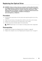
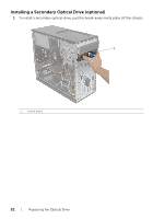
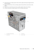
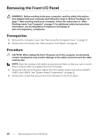
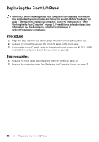
Replacing the Front I/O Panel WARNING: Before working inside your computer, read the safety information that shipped with your computer and follow the steps in "Before You Begin" on page 7. After working inside your computer, follow the instructions in "After Working Inside Your Computer" on page 9. For additional safety best practices information, see the Regulatory Compliance Homepage at dell.com/regulatory_compliance. Procedure 1 Align and slide the front I/O panel clamps into the front I/O panel clamp slot. 2 Replace the screw that secures the front I/O panel to the front panel. 3 Connect the front I/O panel cables to the system board connectors (AUDF1, USBF1, and USBF3). See "System-Board Components" on page 11. Postrequisites 1 Replace the front bezel. See "Replacing the Front Bezel" on page 20. 2 Replace the computer cover. See "Replacing the Computer Cover" on page 13. 36 | Replacing the Front I/O Panel
-
 1
1 -
2
-
3
-
4
-
5
-
6
-
7
-
8
-
9
-
10
-
11
-
12
-
13
-
14
-
15
-
16
-
17
-
18
-
19
-
20
-
21
-
22
-
23
-
24
-
25
-
26
-
27
-
28
-
29
-
30
-
 31
31 -
 32
32 -
 33
33 -
 34
34 -
 35
35 -
 36
36 -
 37
37 -
 38
38 -
 39
39 -
 40
40 -
 41
41 -
42
-
43
-
44
-
45
-
46
-
47
-
48
-
49
-
50
-
51
-
52
-
53
-
54
-
55
 |
 |