Dell Inspiron One 2305 Service Manual
Dell Inspiron One 2305 Manual
 |
View all Dell Inspiron One 2305 manuals
Add to My Manuals
Save this manual to your list of manuals |
Dell Inspiron One 2305 manual content summary:
- Dell Inspiron One 2305 | Service Manual - Page 1
Dell™ Inspiron™ One 2305/2310 Service Manual Technical Overview Before You Begin Back Cover Hard Drive Optical Drive Converter Card Touch Screen Control Card (Optional) Front Stand Audio Video Board Shield Audio Video Board Audio Video Board Cable Audio Video Button Board Rear Stand Cover Rear - Dell Inspiron One 2305 | Service Manual - Page 2
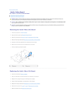
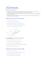
Page Audio Video Board Dell™ Inspiron™ One 2305/2310 Service Manual Removing the Audio Video (AV) Board Replacing the Audio Video (AV) Board WARNING: Before working inside your computer, read the safety information that shipped with your computer. For additional safety best practices information - Dell Inspiron One 2305 | Service Manual - Page 3
CAUTION: Before turning on the computer, replace all screws and ensure that no stray screws remain inside the computer. Failure to do so may result in damage to the computer. 8. Connect your computer and all attached devices to electrical outlets, and turn them on. Back to Contents Page - Dell Inspiron One 2305 | Service Manual - Page 4
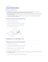
Page Audio Video Board Shield Dell™ Inspiron™ One 2305/2310 Service Manual Removing the Audio Video (AV) Board Shield Replacing the Audio Video (AV) Board Shield WARNING: Before working inside your computer, read the safety information that shipped with your computer. For additional safety best - Dell Inspiron One 2305 | Service Manual - Page 5
Back to Contents Page - Dell Inspiron One 2305 | Service Manual - Page 6
Page Audio Video Board Cable Dell™ Inspiron™ One 2305/2310 Service Manual Removing the Audio Video (AV) Board Cable Replacing the Audio Video (AV) Board Cable WARNING: Before working inside your computer, read the safety information that shipped with your computer. For additional safety best - Dell Inspiron One 2305 | Service Manual - Page 7
on the AV board. 7. Replace the AV board shield (see Replacing the Audio Video (AV) Board Shield). 8. Follow the instructions from step 4 to step 5 in Replacing the Front Stand. 9. Replace the back cover (see Replacing the Back Cover). CAUTION: Before turning on the computer, replace all screws - Dell Inspiron One 2305 | Service Manual - Page 8
Page Audio Video Button Board Dell™ Inspiron™ One 2305/2310 Service Manual Removing the Audio Video (AV) Button Board Replacing the Audio Video (AV) Button Board WARNING: Before working inside your computer, read the safety information that shipped with your computer. For additional safety best - Dell Inspiron One 2305 | Service Manual - Page 9
(see Replacing the Back Cover). CAUTION: Before turning on the computer, replace all screws and ensure that no stray screws remain inside the computer. Failure to do so may result in damage to the computer. 8. Connect your computer and all attached devices to electrical outlets, and turn them on - Dell Inspiron One 2305 | Service Manual - Page 10
to Contents Page Back Cover Dell™ Inspiron™ One 2305/2310 Service Manual Removing the Back Cover Replacing the Back Cover WARNING: Before working inside your computer, read the safety information that shipped with your computer. For additional safety best practices information, see the Regulatory - Dell Inspiron One 2305 | Service Manual - Page 11
CAUTION: Before turning on the computer, replace all screws and ensure that no stray screws remain inside the computer. Failure to do so may result in damage to the computer. 5. Connect your computer and all attached devices to electrical outlets, and turn them on. Back to Contents Page - Dell Inspiron One 2305 | Service Manual - Page 12
Page B-CAS Card (Optional) Dell™ Inspiron™ One 2305/2310 Service Manual Removing the B-CAS Card Replacing the B-CAS Card WARNING: Before working inside your computer, read the safety information that shipped with your computer. For additional safety best practices information, see the Regulatory - Dell Inspiron One 2305 | Service Manual - Page 13
6. Replace the system-board shield (see Removing the System-Board Shield). 7. Follow the instructions from step 4 to step 5 in Replacing the Front Stand. 8. Replace the back cover (see Replacing the Back Cover). CAUTION: Before turning on the computer, replace all screws and ensure that no stray - Dell Inspiron One 2305 | Service Manual - Page 14
Dell™ Inspiron™ One 2305/2310 Service Manual Recommended Tools Turning Off Your Computer Safety Instructions This manual provides procedures for removing and installing the components in your computer Flash BIOS executable update program available at support.dell.com Turning Off Your Computer CAUTION - Dell Inspiron One 2305 | Service Manual - Page 15
electrical outlets. 5. Disconnect all attached devices from your computer. 6. Press and hold the power button while the computer is unplugged to ground the system board. CAUTION: Before touching anything inside your computer, ground yourself by touching an unpainted metal surface, such as the metal - Dell Inspiron One 2305 | Service Manual - Page 16
BIOS Dell™ Inspiron™ One 2305/2310 Service Manual The BIOS may require flashing when an update is available or when replacing the system board. To flash the BIOS: 1. Turn on the computer. 2. Go to support.dell.com/support/downloads. 3. Locate the BIOS update file for your computer: NOTE: The Service - Dell Inspiron One 2305 | Service Manual - Page 17
With Bluetooth® Wireless Technology Dell™ Inspiron™ One 2305/2310 Service Manual Removing the Bluetooth Card Replacing the Bluetooth Card WARNING: Before working inside your computer, read the safety information that shipped with your computer. For additional safety best practices information, see - Dell Inspiron One 2305 | Service Manual - Page 18
bezel over. 6. Follow the instructions from step 2 to step 12 in Replacing the Display Bezel. 7. Replace the system board (See Replacing the System Board). CAUTION: Before turning on the computer, replace all screws and ensure that no stray screws remain inside the computer. Failure to do so may - Dell Inspiron One 2305 | Service Manual - Page 19
Back to Contents Page Camera Module Dell™ Inspiron™ One 2305/2310 Service Manual Removing the Camera Module Replacing the Camera Module WARNING: Before working inside your computer, read the safety information that shipped with your computer. For additional safety best practices information, see the - Dell Inspiron One 2305 | Service Manual - Page 20
bezel over. 6. Follow the instructions from step 2 to step 12 in Replacing the Display Bezel. 7. Replace the system board (See Replacing the System Board). CAUTION: Before turning on the computer, replace all screws and ensure that no stray screws remain inside the computer. Failure to do so may - Dell Inspiron One 2305 | Service Manual - Page 21
Contents Page Wireless Mini-Card(s) Dell™ Inspiron™ One 2305/2310 Service Manual Removing the Mini-Card(s) Replacing the Mini-Card(s) WARNING: Before working inside your computer, read the safety information that shipped with your computer. For additional safety best practices information, see the - Dell Inspiron One 2305 | Service Manual - Page 22
scheme for the Mini- Card(s) supported by your computer. Connectors on the Mini-Card Antenna Cable Color Scheme WLAN (2 antenna cables) Main WLAN (white triangle) white Auxiliary WLAN (black triangle) black TV tuner (1 antenna cable) black 6. Replace the system-board shield (see Replacing the System - Dell Inspiron One 2305 | Service Manual - Page 23
Page Coin-Cell Battery Dell™ Inspiron™ One 2305/2310 Service Manual Removing the Coin-Cell Battery Replacing the Coin-Cell Battery WARNING: Before working inside your computer, read the safety information that shipped with your computer. For additional safety best practices information, see the - Dell Inspiron One 2305 | Service Manual - Page 24
3. Replace the system-board shield (see Replacing the System-Board Shield). 4. Follow the instructions from step 4 to step 5 in Replacing the Front Stand. 5. Replace the back cover (see Replacing the Back Cover). CAUTION: Before turning on the computer, replace all screws and ensure that no stray - Dell Inspiron One 2305 | Service Manual - Page 25
Back to Contents Page Display Dell™ Inspiron™ One 2305/2310 Service Manual Display Bezel Display Panel Display Cable WARNING: Before working inside your computer, read the safety information that shipped with your computer. For additional safety best practices information, see the Regulatory - Dell Inspiron One 2305 | Service Manual - Page 26
Bezel 1. Follow the instructions in Before You Begin. cable, and Bluetooth cable through the routing guides. 10. Adhere the silver foil that secures board (See Replacing the System Board). 14. Replace the AV board (See Replacing the Audio Video (AV) Board). CAUTION: Before turning on the computer - Dell Inspiron One 2305 | Service Manual - Page 27
off the chassis. 1 screws (4) 2 display panel Replacing the Display Panel 1. Follow the instructions in Before You Begin. 2. Route the display cables, touch screen cables, and display panel power cable through the routing guides on the chassis. 3. Align the screw holes on the display panel with - Dell Inspiron One 2305 | Service Manual - Page 28
the Display Cable 1. Follow the instructions in Before You Begin. 2. Connect the display cable to the connector on the display panel. 3. Turn the display panel over. 4. Replace the display panel (see Replacing the Display Panel). CAUTION: Before turning on the computer, replace all screws and ensure - Dell Inspiron One 2305 | Service Manual - Page 29
Back to Contents Page Display Bezel Dell™ Inspiron™ One 2305/2310 Service Manual Removing the Display Bezel Replacing the Display Bezel WARNING: Before working inside your computer, read the safety information that shipped with your computer. For additional safety best practices information, see the - Dell Inspiron One 2305 | Service Manual - Page 30
Follow the instructions in infrared cable, and Bluetooth card cable through the routing guides. 10. Secure the silver foil that connects the camera board (See Replacing the System Board). 14. Replace the AV board (See Replacing the Audio Video (AV) Board). CAUTION: Before turning on the computer - Dell Inspiron One 2305 | Service Manual - Page 31
Page Touch Screen Control Card (Optional) Dell™ Inspiron™ One 2305/2310 Service Manual Removing the Touch Screen Control Card Replacing the Touch Screen Control Card WARNING: Before working inside your computer, read the safety information that shipped with your computer. For additional safety best - Dell Inspiron One 2305 | Service Manual - Page 32
Back to Contents Page - Dell Inspiron One 2305 | Service Manual - Page 33
to Contents Page Front Stand Dell™ Inspiron™ One 2305/2310 Service Manual Removing the Front Stand Replacing the Front Stand WARNING: Before working inside your computer, read the safety information that shipped with your computer. For additional safety best practices information, see the Regulatory - Dell Inspiron One 2305 | Service Manual - Page 34
1. Follow the instructions in Before You Begin. 2. Slide the five tabs on the I/O bracket into the slots on the front stand. 3. Replace the two screws that secure the I/O bracket to the front stand. 4. Align the screw holes on the front-stand assembly with the screw holes on the computer. 5. Replace - Dell Inspiron One 2305 | Service Manual - Page 35
Back to Contents Page Hard Drive Dell™ Inspiron™ One 2305/2310 Service Manual Removing the Hard Drive Replacing the Hard Drive WARNING: Before working inside your computer, read the safety information that shipped with your computer. For additional safety best practices information, see the - Dell Inspiron One 2305 | Service Manual - Page 36
hard drive 2 hard-drive cage Replacing the Hard Drive 1. Follow the instructions in Before You Begin. 2. Place the hard-drive cage on the hard drive, and align the screw holes on the hard-drive cage with the screw holes on the hard drive. 3. Replace the four screws that secure the hard-drive cage - Dell Inspiron One 2305 | Service Manual - Page 37
Page Processor Heat-Sink Dell™ Inspiron™ One 2305/2310 Service Manual Removing the Processor Heat Sink Replacing the Processor Heat Sink WARNING: Before working inside your computer, read the safety information that shipped with your computer. For additional safety best practices information, see - Dell Inspiron One 2305 | Service Manual - Page 38
shield (see Replacing the System-Board Shield). 9. Follow the instructions from step 4 to step 5 in Replacing the Front Stand. 10. Replace the back cover (see Replacing the Back Cover). CAUTION: Before turning on the computer, replace all screws and ensure that no stray screws remain inside the - Dell Inspiron One 2305 | Service Manual - Page 39
Heat-Sink Fan Dell™ Inspiron™ One 2305/2310 Service Manual Removing the Processor Heat-Sink Fan Replacing the Processor Heat-Sink Fan WARNING: Before working inside your computer, read the safety information that shipped with your computer. For additional safety best practices information, see - Dell Inspiron One 2305 | Service Manual - Page 40
. 6. Replace the system-board shield (see Replacing the System-Board Shield). 7. Follow the instructions from step 4 to step 5 in Replacing the Front Stand. 8. Replace the back cover (see Replacing the Back Cover). CAUTION: Before turning on the computer, replace all screws and ensure that no stray - Dell Inspiron One 2305 | Service Manual - Page 41
to Contents Page Converter Card Dell™ Inspiron™ One 2305/2310 Service Manual Removing the Converter Card Replacing the Converter Card WARNING: Before working inside your computer, read the safety information that shipped with your computer. For additional safety best practices information, see the - Dell Inspiron One 2305 | Service Manual - Page 42
Back to Contents Page - Dell Inspiron One 2305 | Service Manual - Page 43
Blaster Connector Dell™ Inspiron™ One 2305/2310 Service Manual Removing the Infrared (IR) Blaster Connector Replacing the Infrared (IR) Blaster Connector WARNING: Before working inside your computer, read the safety information that shipped with your computer. For additional safety best practices - Dell Inspiron One 2305 | Service Manual - Page 44
CAUTION: Before turning on the computer, replace all screws and ensure that no stray screws remain inside the computer. Failure to do so may result in damage to the computer. 7. Connect your computer and all attached devices to electrical outlets, and turn them on. Back to Contents Page - Dell Inspiron One 2305 | Service Manual - Page 45
Back to Contents Page Infrared Card Dell™ Inspiron™ One 2305/2310 Service Manual Removing the Infrared Card Replacing the Infrared Card WARNING: Before working inside your computer, read the safety information that shipped with your computer. For additional safety best practices information, see the - Dell Inspiron One 2305 | Service Manual - Page 46
bezel over. 6. Follow the instructions from step 2 to step 12 in Replacing the Display Bezel. 7. Replace the system board (See Replacing the System Board). CAUTION: Before turning on the computer, replace all screws and ensure that no stray screws remain inside the computer. Failure to do so may - Dell Inspiron One 2305 | Service Manual - Page 47
to Contents Page Memory Module(s) Dell™ Inspiron™ One 2305/2310 Service Manual Removing Memory Module(s) Replacing Memory Module(s) WARNING: Before working inside your computer, read the safety information that shipped with your computer. For additional safety best practices information, see the - Dell Inspiron One 2305 | Service Manual - Page 48
system-board shield. 6. Lift the memory-module cover away from the system-board shield. 1 captive screw 3 memory-module cover 2 system-board Memory Module(s) Inspiron One 2305 CAUTION: If the memory module is not installed properly, the computer may not boot. 1. Follow the instructions in Before - Dell Inspiron One 2305 | Service Manual - Page 49
screw that secures the memory-module cover to the system-board shield. 7. Follow the instructions from step 4 to step 5 in Replacing the Security® System. Inspiron One 2310 CAUTION: If the memory module is not installed properly, the computer may not boot. 1. Follow the instructions in Before You - Dell Inspiron One 2305 | Service Manual - Page 50
screw that secures the memory-module cover to the system-board shield. 6. Replace the back cover (see Replacing the Back Cover). 7. Follow the instructions from step 4 to step 5 in Replacing the Front Stand. CAUTION: Before turning on the computer, replace all screws and ensure that no stray screws - Dell Inspiron One 2305 | Service Manual - Page 51
Back to Contents Page Middle Frame Dell™ Inspiron™ One 2305/2310 Service Manual Removing the Middle Frame Replacing the Middle Frame WARNING: Before working inside your computer, read the safety information that shipped with your computer. For additional safety best practices information, see the - Dell Inspiron One 2305 | Service Manual - Page 52
CAUTION: Before turning on the computer, replace all screws and ensure that no stray screws remain inside the computer. Failure to do so may result in damage to the computer. 7. Connect your computer and all attached devices to electrical outlets, and turn them on. Back to Contents Page - Dell Inspiron One 2305 | Service Manual - Page 53
MXM-Assembly Fan (Optional) Dell™ Inspiron™ One 2305/2310 Service Manual Removing the MXM-Assembly Fan Replacing the MXM-Assembly Fan WARNING: Before working inside your computer, read the safety information that shipped with your computer. For additional safety best practices information, see the - Dell Inspiron One 2305 | Service Manual - Page 54
. 6. Replace the system-board shield (see Replacing the System-Board Shield). 7. Follow the instructions from step 4 to step 5 in Replacing the Front Stand. 8. Replace the back cover (see Replacing the Back Cover). CAUTION: Before turning on the computer, replace all screws and ensure that no stray - Dell Inspiron One 2305 | Service Manual - Page 55
Contents Page MXM Assembly (Optional) Dell™ Inspiron™ One 2305/2310 Service Manual Removing the MXM Assembly Replacing the MXM Assembly WARNING: Before working inside your computer, read the safety information that shipped with your computer. For additional safety best practices information, see the - Dell Inspiron One 2305 | Service Manual - Page 56
-Assembly Fan). 6. Replace the system-board shield (see Replacing the System-Board Shield). 7. Follow the instructions from step 4 to step 5 in Replacing the Front Stand. 8. Replace the back cover (see Replacing the Back Cover). CAUTION: Before turning on the computer, replace all screws and ensure - Dell Inspiron One 2305 | Service Manual - Page 57
Back to Contents Page Optical Drive Dell™ Inspiron™ One 2305/2310 Service Manual Removing the Optical Drive Replacing the Optical Drive WARNING: Before working inside your computer, read the safety information that shipped with your computer. For additional safety best practices information, see the - Dell Inspiron One 2305 | Service Manual - Page 58
bezel 2 optical-drive bracket Replacing the Optical Drive 1. Follow the instructions in Before You Begin. 2. Align the tabs on the optical-drive bezel with the slots on the optical drive and snap the optical-drive bezel into place. 3. Align the screw holes on the optical-drive bracket with the - Dell Inspiron One 2305 | Service Manual - Page 59
Back to Contents Page Processor Dell™ Inspiron™ One 2305/2310 Service Manual Removing the Processor Replacing the Processor WARNING: Before working inside your computer, read the safety information that shipped with your computer. For additional safety best practices information, see the Regulatory - Dell Inspiron One 2305 | Service Manual - Page 60
instructions in Before You Begin. 2. Unpack and replace new processor: CAUTION: Ground yourself by touching an unpainted metal surface or the computer stand. Inspiron One 2305 install the processor. Be careful not to touch or bend the pins on the system board. CAUTION: You must position the processor - Dell Inspiron One 2305 | Service Manual - Page 61
of the processor. Inspiron One 2310 CAUTION: Socket pins are delicate. To avoid damage, ensure that the processor is aligned properly with the processor socket, and do not use excessive force when you install the processor. Be careful not to touch or bend the pins on the system board. CAUTION: You - Dell Inspiron One 2305 | Service Manual - Page 62
CAUTION: Before turning on the computer, replace all screws and ensure that no stray screws remain inside the computer. Failure to do so may result in damage to the computer. 10. Connect your computer and all attached devices to electrical outlets, and then turn them on. Back to Contents Page - Dell Inspiron One 2305 | Service Manual - Page 63
Page System-Board Shield Dell™ Inspiron™ One 2305/2310 Service Manual Removing the System-Board Shield Replacing the System-Board Shield WARNING: Before working inside your computer, read the safety information that shipped with your computer. For additional safety best practices information - Dell Inspiron One 2305 | Service Manual - Page 64
Replace the four screws that secure the system-board shield to the chassis. 9. Follow the instructions from step 4 to step 5 in Replacing the Front Stand. 10. Replace the back cover (see Replacing the Back Cover). CAUTION: Before turning on the computer, replace all screws and ensure that no stray - Dell Inspiron One 2305 | Service Manual - Page 65
Back to Contents Page Speakers Dell™ Inspiron™ One 2305/2310 Service Manual Removing the Speakers Replacing the Speakers WARNING: Before working inside your computer, read the safety information that shipped with your computer. For additional safety best practices information, see the Regulatory - Dell Inspiron One 2305 | Service Manual - Page 66
the connector on the system board. 6. Replace the system-board shield (see Replacing the System-Board Shield). 7. Replace the middle frame (see Replacing the Middle Frame). 8. Follow the instructions from step 5 to step 7 in Replacing the Optical Drive. 9. Follow the instructions from step 4 to step - Dell Inspiron One 2305 | Service Manual - Page 67
Back to Contents Page Speaker Cover Dell™ Inspiron™ One 2305/2310 Service Manual Removing the Speaker Cover Replacing the Speaker Cover WARNING: Before working inside your computer, read the safety information that shipped with your computer. For additional safety best practices information, see the - Dell Inspiron One 2305 | Service Manual - Page 68
Replacing the System Board). 7. Replace the speakers (see Replacing the Speakers). CAUTION: Before turning on the computer, replace all screws and ensure that no stray screws remain inside the computer. Failure to do so may result in damage to the computer. 8. Connect your computer and all attached - Dell Inspiron One 2305 | Service Manual - Page 69
to Contents Page Rear Stand Dell™ Inspiron™ One 2305/2310 Service Manual Removing the Rear Stand Replacing the Rear Stand WARNING: Before working inside your computer, read the safety information that shipped with your computer. For additional safety best practices information, see the Regulatory - Dell Inspiron One 2305 | Service Manual - Page 70
(see Replacing the Back Cover). CAUTION: Before turning on the computer, replace all screws and ensure that no stray screws remain inside the computer. Failure to do so may result in damage to the computer. 8. Connect your computer and all attached devices to electrical outlets, and turn them on - Dell Inspiron One 2305 | Service Manual - Page 71
Page Rear Stand Cover Dell™ Inspiron™ One 2305/2310 Service Manual Removing the Rear Stand Cover Replacing the Rear Stand Cover WARNING: Before working inside your computer, read the safety information that shipped with your computer. For additional safety best practices information, see the - Dell Inspiron One 2305 | Service Manual - Page 72
Back to Contents Page - Dell Inspiron One 2305 | Service Manual - Page 73
Page System Board Dell™ Inspiron™ One 2305/2310 Service Manual Removing the System Board Replacing the System Board Entering the Service Tag in the BIOS WARNING: Before working inside your computer, read the safety information that shipped with your computer. For additional safety best practices - Dell Inspiron One 2305 | Service Manual - Page 74
damage to the computer. 16. Turn on the computer. NOTE: After you have replaced the system board, enter the computer's Service Tag into the BIOS of the replacement system board. 17. Enter the Service Tag (see Entering the Service Tag in the BIOS). Entering the Service Tag in the BIOS 1. Turn on the - Dell Inspiron One 2305 | Service Manual - Page 75
2. Press during POST to enter the system setup program. 3. Navigate to the main tab and enter the service tag in the Service Tag Setting field. Back to Contents Page - Dell Inspiron One 2305 | Service Manual - Page 76
Utility Dell™ Inspiron™ One 2305/2310 Service Manual Overview Clearing Forgotten Passwords Clearing CMOS Passwords Overview Use the system setup utility to: l Change the system configuration information after you add, change, or remove any hardware in your computer l Set or change a user-selectable - Dell Inspiron One 2305 | Service Manual - Page 77
Specifies the boot sequence from the available devices Diskette Drive; Hard Drive; USB Storage Device; CD/DVD/CD-RW Drive; Network; Disabled (USB Storage Device by default) Exit Exit Options Provides options to Save Changes and Reset, Discard Changes and Reset, and Load Defaults Inspiron One 2310 - Dell Inspiron One 2305 | Service Manual - Page 78
Technology Device Information SATA 0 SATA 1 Displays the system name Displays the BIOS version number Displays the current date in mm/dd/yyyy format Displays the current time in hh:mm:ss format Displays the service tag of the computer when the service tag is present Displays the asset tag of the - Dell Inspiron One 2305 | Service Manual - Page 79
in the drive, or if the CD/DVD/CD-RW has no operating system, the computer generates an error message. l USB Storage Device - Insert the memory device into a USB connector and restart the computer. When F12 Boot Options appears in the lower-right corner of the screen, press . The BIOS detects - Dell Inspiron One 2305 | Service Manual - Page 80
Cover). 3. Remove the system-board shield (see Removing the System-Board Shield). 4. Locate the 3-pin password reset jumper (CLR_PWSD) on the system board. (see System Board Components). 5. Remove the 2-pin jumper plug from pins 2 and 3 and fix it on pins 1 and 2. Inspiron One 2305 Inspiron One 2310 - Dell Inspiron One 2305 | Service Manual - Page 81
see Removing the Back Cover). 3. Remove the system-board shield (see Removing the System-Board Shield). 4. Locate the 3-pin CMOS reset jumper (CLR_CMOS) on the system board. (see System Board Components). 5. Remove the 2-pin jumper plug from pins 2 and 3 and fix it on pins 1 and 2. Inspiron One 2305 - Dell Inspiron One 2305 | Service Manual - Page 82
Inspiron One 2310 6. Wait for approximately five seconds to clear the CMOS setting. 7. Remove the 2-pin jumper plug from pins 1 and 2 and replace it on pins 2 and 3. 8. Replace the system-board shield (see Replacing the System-Board Shield). 9. Replace the back cover (see Replacing the Back Cover). - Dell Inspiron One 2305 | Service Manual - Page 83
Contents Page Technical Overview Dell™ Inspiron™ One 2305/2310 Service Manual Inside View of Your Inspiron One System Board Components WARNING: Before working inside your computer, read the safety information that shipped with your computer. For additional safety best practices information, see the - Dell Inspiron One 2305 | Service Manual - Page 84
1 TV tuner card slot (TV TUNER) 2 SATA connector (ODD) 3 touch-screen cable connector 4 Mini-Card slot (WLAN\COMBO) (Touch) 5 Bluetooth cable connector (BT) 6 display cable connector (when both MXM card and audio video card are present) (AV IN_MXM) 7 display cable connector (when only MXM card - Dell Inspiron One 2305 | Service Manual - Page 85
Mini-Card slot (WLAN\COMBO) 3 CMOS jumper (CLR_CMOS) 4 password jumper (CLR_PSWD) 5 SATA drive connector (SATA 1) 6 SATA drive connector (SATA 0) 7 display cable connector (when 8 display cable connector (when both MXM card and audio video only MXM card is present) card are present) (AVIN_MXM - Dell Inspiron One 2305 | Service Manual - Page 86
Back to Contents Page Dell™ Inspiron™ One 2305/2310 Service Manual NOTE: A NOTE indicates important information that helps you make better use of your computer. CAUTION: A CAUTION indicates either potential damage to hardware or loss of data and tells you how to avoid the problem. WARNING: A WARNING - Dell Inspiron One 2305 | Service Manual - Page 87
Page Antenna-In Connector Dell™ Inspiron™ One 2305/2310 Service Manual Removing the Antenna-In Connector Replacing the Antenna-In Connector WARNING: Before working inside your computer, read the safety information that shipped with your computer. For additional safety best practices information, see - Dell Inspiron One 2305 | Service Manual - Page 88
(see Replacing the Back Cover). CAUTION: Before turning on the computer, replace all screws and ensure that no stray screws remain inside the computer. Failure to do so may result in damage to the computer. 7. Connect your computer and all attached devices to electrical outlets, and turn them on - Dell Inspiron One 2305 | Service Manual - Page 89
to Contents Page Wireless Antenna Dell™ Inspiron™ One 2305/2310 Service Manual Removing the Wireless Antenna Replacing the Wireless Antenna WARNING: Before working inside your computer, read the safety information that shipped with your computer. For additional safety best practices information, see - Dell Inspiron One 2305 | Service Manual - Page 90
6. Connect your computer and all attached devices to electrical outlets, and turn them on. Back to Contents Page
-
 1
1 -
 2
2 -
 3
3 -
 4
4 -
 5
5 -
 6
6 -
 7
7 -
8
-
9
-
10
-
11
-
12
-
13
-
14
-
15
-
16
-
17
-
18
-
19
-
20
-
21
-
22
-
23
-
24
-
25
-
26
-
27
-
28
-
29
-
30
-
31
-
32
-
33
-
34
-
35
-
36
-
37
-
38
-
39
-
40
-
41
-
42
-
43
-
44
-
45
-
46
-
47
-
48
-
49
-
50
-
51
-
52
-
53
-
54
-
55
-
56
-
57
-
58
-
59
-
60
-
61
-
62
-
63
-
64
-
65
-
66
-
67
-
68
-
69
-
70
-
71
-
72
-
73
-
74
-
75
-
76
-
77
-
78
-
79
-
80
-
81
-
82
-
83
-
84
-
85
-
86
-
87
-
88
-
89
-
90
 |
 |
Dell™ Inspiron™ One 2305/2310 Service Manual
Notes, Cautions, and Warnings
Information in this document is subject to change without notice.
© 2010 Dell Inc. All rights reserved.
Reproduction of these materials in any manner whatsoever without the written permission of Dell Inc. is strictly forbidden.
Trademarks used in this text:
Dell
, the
DELL
logo, and
Inspiron
are trademarks of Dell Inc.;
Bluetooth
is a registered trademark owned by Bluetooth SIG, Inc. and is used by Dell
under license;
Microsoft
,
Windows
,
and the
Windows
start button logo
are either trademarks or registered trademarks of Microsoft Corporation in the United States and/or other
countries.
Other trademarks and trade names may be used in this document to refer to either the entities claiming the marks and names or their products. Dell Inc. disclaims any
proprietary interest in trademarks and trade names other than its own.
August 2010
Rev. A00
Regulatory model: W01C series Regulatory type: W01C001; W01C002
Technical Overview
Before You Begin
Back Cover
Hard Drive
Optical Drive
Converter Card
Touch Screen Control Card (Optional)
Front Stand
Audio Video Board Shield
Audio Video Board
Audio Video Board Cable
Audio Video Button Board
Rear Stand Cover
Rear Stand
Middle Frame
System
-
Board Shield
Antenna
-
In Connector
Infrared Blaster Connector
Wireless Antenna
Memory Module(s)
Wireless Mini
-
Card(s)
Coin
-
Cell Battery
MXM
-
Assembly Fan (Optional)
MXM Assembly (Optional)
Processor Heat
-
Sink Fan
Processor Heat
-
Sink
Processor
Speakers
Speaker Cover
System Board
Internal Card With Bluetooth
®
Wireless Technology
Camera Module
Infrared Card
B
-
CAS Card (Optional)
Display
System Setup Utility
Flashing the BIOS
NOTE:
A NOTE indicates important information that helps you make better use of your computer.
CAUTION:
A CAUTION indicates either potential damage to hardware or loss of data and tells you how to avoid the problem.
WARNING:
A WARNING indicates a potential for property damage, personal injury, or death.