Dell Latitude ATG D620 Service Manual - Page 29
Modem
 |
View all Dell Latitude ATG D620 manuals
Add to My Manuals
Save this manual to your list of manuals |
Page 29 highlights
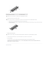
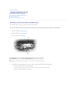
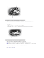
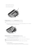
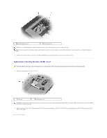
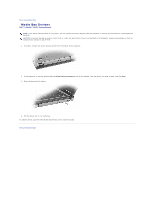
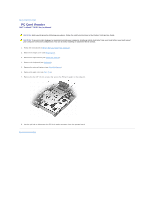
Back to Contents Page Modem Dell™ Latitude™ D620 Service Manual CAUTION: Before you begin the following procedure, see the safety instructions in the Product Information Guide. NOTICE: To avoid damaging the system board, you must remove the main battery before you begin working inside the computer (see Before Working Inside Your Computer). CAUTION: To prevent static damage to components inside your computer, discharge static electricity from your body before you touch any of your computer's electronic components. You can do so by touching an unpainted metal surface. 1. Follow the instructions in Before Working Inside Your Computer. 2. Remove the hinge cover (see Hinge Cover). 3. Remove the optical drive (see Media Bay Devices). 4. Remove the keyboard (see Keyboard). 5. Remove the coin-cell battery (see Coin-Cell Battery). 6. Remove the display assembly (see Display Assembly). 7. Remove the palm rest (see Palm Rest). 8. Remove the M2 x 3-mm screw that attaches the modem to the system board. 9. Pull up on the pull-tab to disconnect the modem from the connector on the system board. 1 modem pull-tab 4 system board connector 2 M2 x 3-mm screw 3 modem cable NOTICE: Do not disconnect the modem cable from the system board. 10. Disconnect the modem cable from the modem. Back to Contents Page
-
 1
1 -
2
-
3
-
4
-
5
-
6
-
7
-
8
-
9
-
10
-
11
-
12
-
13
-
14
-
15
-
16
-
17
-
18
-
19
-
20
-
21
-
22
-
23
-
 24
24 -
 25
25 -
 26
26 -
 27
27 -
 28
28 -
 29
29 -
 30
30 -
 31
31 -
 32
32 -
 33
33 -
 34
34 -
35
-
36
-
37
-
38
-
39
-
40
-
41
-
42
-
43
 |
 |
