Dell OptiPlex FX160 Setup and Quick Reference Guide - Page 13
Front panel LED, Mini-PCI Express X1 - i o board
 |
View all Dell OptiPlex FX160 manuals
Add to My Manuals
Save this manual to your list of manuals |
Page 13 highlights
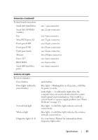
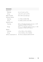
Connectors (continued) System board connectors: Serial ATA (hard drive) Serial ATA (NVRAM module) Fan Mini-PCI Express X1 Front panel LED Front panel USB Front panel audio Memory Power 12 V BIOS ROM Serial ATA hard drive power Controls and Lights Front of computer: Power button Power light (within the power button) Network link light Wireless light Diagnostic lights (1-4) one 7-pin connector one 22-pin connector one 5-pin connector one 52-pin connector one 14-pin connector two 10-pin connectors one 12-pin connector two 240-pin connectors one 4-pin connector one 8-pin socket one 4-pin connector push button blue light - Blinking blue in sleep state; solid blue for power on state. amber light - A solid amber light when the computer does not start indicates that the system board cannot start initialization. This could be a system board or a power supply problem (see "Power Problems" on page 17). blue light - A solid blue light indicates network connectivity. blue light - A solid blue light indicates the wireless network is powered on. See your Service Manual for information about diagnostic light codes. Specifications 13
-
 1
1 -
2
-
3
-
4
-
5
-
6
-
7
-
 8
8 -
 9
9 -
 10
10 -
 11
11 -
 12
12 -
 13
13 -
 14
14 -
 15
15 -
 16
16 -
 17
17 -
 18
18 -
19
-
20
-
21
-
22
-
23
-
24
-
25
-
26
-
27
-
28
-
29
-
30
-
31
-
32
-
33
-
34
-
35
-
36
-
37
-
38
-
39
-
40
-
41
-
42
 |
 |
