Dell PowerConnect W-IAP Remote Getting Started Guide - Page 11
General precautions, Never leave tools inside the device.
 |
View all Dell PowerConnect W-IAP Remote manuals
Add to My Manuals
Save this manual to your list of manuals |
Page 11 highlights
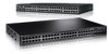
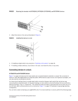
Installation location Before installing the device, plan its location and orientation relative to other devices and equipment. Switches can be mounted in a standard 19-inch equipment rack that meets EIA-310D standards, or on a flat surface. Be sure to follow the guidelines below when choosing a location. The site should meet the following requirements: • Maintain temperatures within 0 to 40οC (32 to 104οF) and humidity levels within 5% to 95%, non-condensing. • Allow a minimum of 7.62 cm (3 in.) of space between the sides and the back of the device and walls or other obstructions for proper air flow. • Allow at least 3 in. of space at the front and back of the device for the twisted-pair, fiber-optic, and power cabling. • Be accessible for installing, cabling and maintaining the devices. • Allow the status LEDs to be clearly visible. • Allow for twisted-pair cable to be always routed away from power lines, fluorescent lighting fixtures and other sources of electrical interference, such as radios and transmitters. • Allow for the unit to be connected to a separate grounded power outlet that provides 110 to 240 VAC, 50 to 60 Hz, is within 2 m (6.6 feet) of each device and is powered from an independent circuit breaker. As with any equipment, a filter or surge suppressor is recommended. General precautions CAUTION All fiber-optic interfaces use Class 1 lasers. CAUTION Do not install the device in an environment where the operating ambient temperature might exceed 40ο C (104ο F). CAUTION Make sure the air flow around the front and sides of the device is not restricted. CAUTION Never leave tools inside the device. PowerConnect B-Series FCX/FCXS Getting Started Guide 9 53-1002049-01
-
 1
1 -
2
-
3
-
4
-
5
-
 6
6 -
 7
7 -
 8
8 -
 9
9 -
 10
10 -
 11
11 -
 12
12 -
 13
13 -
 14
14 -
 15
15 -
 16
16 -
17
-
18
-
19
-
20
-
21
-
22
-
23
-
24
-
25
-
26
-
27
-
28
-
29
-
30
-
31
-
32
-
33
-
34
-
35
-
36
-
37
-
38
-
39
-
40
-
41
-
42
-
43
-
44
-
45
-
46
-
47
-
48
-
49
-
50
-
51
-
52
-
53
-
54
-
55
-
56
-
57
-
58
-
59
-
60
-
61
-
62
-
63
-
64
-
65
-
66
-
67
-
68
-
69
-
70
-
71
-
72
-
73
-
74
-
75
-
76
-
77
-
78
-
79
-
80
-
81
-
82
-
83
-
84
-
85
-
86
-
87
-
88
-
89
-
90
-
91
-
92
-
93
-
94
-
95
-
96
-
97
-
98
-
99
-
100
-
101
-
102
-
103
-
104
-
105
-
106
-
107
-
108
-
109
-
110
-
111
-
112
-
113
-
114
-
115
-
116
-
117
-
118
-
119
-
120
-
121
-
122
-
123
-
124
-
125
-
126
-
127
-
128
-
129
-
130
-
131
-
132
-
133
-
134
-
135
-
136
-
137
-
138
-
139
-
140
-
141
-
142
-
143
-
144
-
145
-
146
-
147
-
148
-
149
-
150
-
151
-
152
-
153
-
154
-
155
-
156
-
157
-
158
-
159
-
160
-
161
-
162
-
163
-
164
-
165
-
166
-
167
-
168
-
169
-
170
-
171
-
172
-
173
-
174
-
175
-
176
-
177
-
178
-
179
-
180
-
181
-
182
-
183
-
184
-
185
-
186
-
187
-
188
-
189
-
190
-
191
-
192
-
193
-
194
-
195
-
196
-
197
-
198
-
199
-
200
-
201
-
202
-
203
-
204
-
205
-
206
-
207
-
208
-
209
-
210
-
211
-
212
-
213
-
214
-
215
-
216
-
217
-
218
-
219
-
220
-
221
-
222
-
223
-
224
-
225
-
226
-
227
-
228
-
229
-
230
-
231
-
232
-
233
-
234
-
235
-
236
-
237
-
238
-
239
-
240
-
241
-
242
-
243
-
244
-
245
-
246
-
247
-
248
-
249
-
250
-
251
-
252
-
253
-
254
-
255
-
256
-
257
-
258
-
259
-
260
 |
 |
