Dell PowerEdge 4600 Removing the Back Fan Assembly - Page 1
Dell PowerEdge 4600 Manual
 |
View all Dell PowerEdge 4600 manuals
Add to My Manuals
Save this manual to your list of manuals |
Page 1 highlights
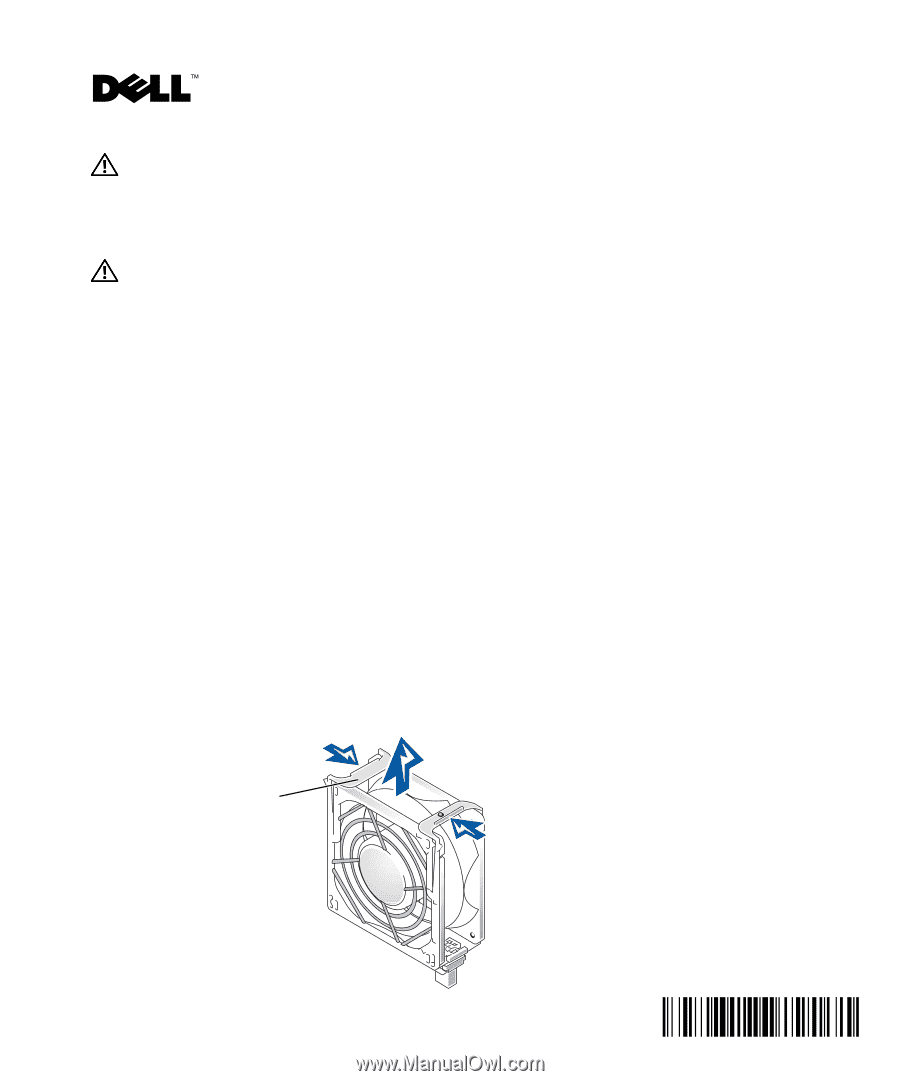
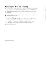
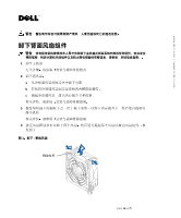
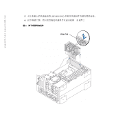
www.dell.com | support.dell.com CAUTION: A CAUTION indicates a potential for property damage, personal injury, or death. Removing the Back Fan Assembly CAUTION: Only trained service technicians are authorized to remove the system cover and access any of the components inside the system. See your System Information Guide for complete information about safety precautions, working inside the computer, and protecting against electrostatic discharge. 1 Remove the system cover. See your Installation and Troubleshooting Guide for detailed information. 2 Remove the cooling shroud. a Remove the cables from the cooling shroud's retaining clips. b Loosen the two thumbscrews securing the cooling shroud to the system. c Lift the cooling shroud up to clear the memory riser cards and the chassis. See your Installation and Troubleshooting Guide for detailed information. 3 Remove the memory riser cards by grasping each card by the extractor tabs, located on the top corners of the card, and lifting it straight up to clear the chassis. See your Installation and Troubleshooting Guide for detailed information. 4 Remove the four fans by squeezing the fan release levers and lifting each fan straight up to clear the fan assembly (see Figure 1). Figure 1. Removing/Replacing a Fan release lever April 2003 0C1553A01
-
 1
1 -
 2
2 -
 3
3 -
 4
4 -
 5
5 -
 6
6 -
 7
7 -
8
-
9
-
10
-
11
-
12
-
13
-
14
-
15
-
16
-
17
-
18
-
19
-
20
-
21
-
22
-
23
-
24
-
25
-
26
-
27
-
28
 |
 |