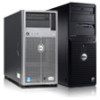
Dell PowerEdge C8000 Dell PowerEdge C8000 Hardware Owner's Manual
Dell PowerEdge C8000 Manual
 |
View all Dell PowerEdge C8000 manuals
Add to My Manuals
Save this manual to your list of manuals |
Dell PowerEdge C8000 manual content summary:
- Dell PowerEdge C8000 | Dell PowerEdge C8000 Hardware Owner's Manual - Page 1
Dell PowerEdge C8000 Hardware Owner's Manual Regulatory Model: B10S Regulatory Type: B10S001 - Dell PowerEdge C8000 | Dell PowerEdge C8000 Hardware Owner's Manual - Page 2
A CAUTION indicates potential damage to hardware or loss of data if instructions are not followed. WARNING: A WARNING indicates a potential for property permission of Dell Inc. is strictly forbidden. Trademarks used in this text: Dell™, the DELL logo, PowerEdge™ are trademarks of Dell Inc. Intel - Dell PowerEdge C8000 | Dell PowerEdge C8000 Hardware Owner's Manual - Page 3
11 Back-Panel Features and Indicators 12 Server Enclosure Indicator Codes 14 NIC Indicator Codes 16 Sled Bay Numbering 18 Fan Bay Numbering 19 Sled Module Configuration 20 Sled Features 21 Power Sleds 21 Compute Sleds 23 Storage Sleds 29 Service Tag 31 POST Error Codes 35 Collecting - Dell PowerEdge C8000 | Dell PowerEdge C8000 Hardware Owner's Manual - Page 4
62 General Help 63 Console Redirection 63 Enabling and Configuring Console Redirection 63 Main Menu 68 Main Screen 68 System Settings 69 Advanced Menu 71 Power Management 72 CPU Configuration 78 Memory Configuration 81 SATA Configuration 83 4 Contents - Dell PowerEdge C8000 | Dell PowerEdge C8000 Hardware Owner's Manual - Page 5
Power Management Settings 138 3 Installing System Components 141 Safety Instructions 141 Recommended Tools 142 Inside the System 143 Sled Blank 144 Removing a Sled Blank 144 Installing a Sled Blank 144 Compute Sleds 145 Removing a Compute Sled 145 Installing a Compute Sled 146 Storage - Dell PowerEdge C8000 | Dell PowerEdge C8000 Hardware Owner's Manual - Page 6
163 Removing the Fan Controller Board 163 Installing the Fan Controller Board 164 4 Troubleshooting 165 Safety First-For You and Your System 165 Installation Problems 165 Troubleshooting System Startup Failure 166 Troubleshooting External Connections 166 Troubleshooting the Video Subsystem - Dell PowerEdge C8000 | Dell PowerEdge C8000 Hardware Owner's Manual - Page 7
Board 178 Troubleshooting the System Battery 179 IRQ Assignment Conflicts 180 5 Jumpers and Connectors 181 Server Enclosure Boards 181 Front Panel Board Connectors 181 Fan Controller Board Connectors 182 Power Management Board Connectors 183 Power Sled Boards 184 Power Distribution Boards - Dell PowerEdge C8000 | Dell PowerEdge C8000 Hardware Owner's Manual - Page 8
6 Getting Help 187 Contacting Dell 187 Index 189 8 Contents - Dell PowerEdge C8000 | Dell PowerEdge C8000 Hardware Owner's Manual - Page 9
C8000XD storage sleds. A mixed sled enclosure can support a mixture of differing sled types. To function as a system, a compute sled is inserted into the PowerEdge C8000 server enclosure that supports fans and optional power sleds. The fans are shared resources of the sleds in the PowerEdge C8000 - Dell PowerEdge C8000 | Dell PowerEdge C8000 Hardware Owner's Manual - Page 10
Accessing System Features During Startup The following keystrokes provide access to system features during startup. The SAS/SATA card or PXE hotkey support are available only in the BIOS boot mode. Hotkey function is not available in the Unified Extensible Firmware Interface (UEFI) boot mode. - Dell PowerEdge C8000 | Dell PowerEdge C8000 Hardware Owner's Manual - Page 11
or a combination of the two sled types. NOTE: If the enclosure is configured with only one power sled, a C8220 compute sled or a power sled blank must be mounted into the adjacent sled bay. Indicates the power and health status of the whole system. Lights blue when the chassis ID signal is generated - Dell PowerEdge C8000 | Dell PowerEdge C8000 Hardware Owner's Manual - Page 12
NIC link/activity indicator Indicates state of the network link and activity. Back-Panel Features and Indicators Figure 1-2. Back-Panel Features and Indicators Item Feature 1 Fan modules Icon Description Provides cooling solution to the enclosure. 12 About the System - Dell PowerEdge C8000 | Dell PowerEdge C8000 Hardware Owner's Manual - Page 13
or storage sled to the front of the enclosure, install the power sleds and connect power to the enclosure. Indicates the function status of the system fans. Press this button to enter service mode. Connects to a PDU control connector. Dedicated management port. Lights blue when the chassis ID - Dell PowerEdge C8000 | Dell PowerEdge C8000 Hardware Owner's Manual - Page 14
Off Solid Blinking Off Indicator Code Indicates a valid power source is connected to the server enclosure and that the enclosure is operational. Power is not connected. Indicates a fault event occurred. Indicates a chassis ID signal is generated. Chassis ID signal is not generated. Linking at 100 - Dell PowerEdge C8000 | Dell PowerEdge C8000 Hardware Owner's Manual - Page 15
is connected to the server enclosure and that the enclosure is operational and power is applied to the fan controller board. Power is connected to the enclosure but the managed devices' or sleds' power is off. Indicates a fault event occurred. Power is not connected. Indicates a chassis ID signal is - Dell PowerEdge C8000 | Dell PowerEdge C8000 Hardware Owner's Manual - Page 16
Amber Off Status Blinking Off Blinking Off Indicator Code Indicates a fault event occurred in fans 3 and 4. Fans 3 and 4 are operational. Indicates a fault event occurred in fans 5 and 6. Fans 5 and 6 are operational. NIC Indicator Codes Figure 1-5. NIC Indicators (Front-Panel Ethernet Connector - Dell PowerEdge C8000 | Dell PowerEdge C8000 Hardware Owner's Manual - Page 17
Figure 1-6. NIC Indicators (BMC management port) 1 link indicator 2 activity indicator Indicator Status Link indicator Blinking amber Blinking green Activity indicator Solid green Blinking green Off Indicator Code Linking at 10 Mbps port speed Linking at 100 Mbps port speed (maximum) No - Dell PowerEdge C8000 | Dell PowerEdge C8000 Hardware Owner's Manual - Page 18
single-wide compute sled or a power sled occupies one sled bay in the server enclosure and a C8220X double-wide compute sled or C8000XD storage sled occupies two sled bays in the server enclosure. When installing a sled module into the server enclosure, you should install the sled module in sled bay - Dell PowerEdge C8000 | Dell PowerEdge C8000 Hardware Owner's Manual - Page 19
PowerEdge C8000 server enclosure includes three hotswappable fan modules that provide the system with redundant cooling source. Each fan module contains two cooling fans. All three fan modules must be installed at all times to ensure proper cooling. Figure 1-8. Fan Bay Numbering Fan Bay Fan module - Dell PowerEdge C8000 | Dell PowerEdge C8000 Hardware Owner's Manual - Page 20
configurations available on the PowerEdge C8000 server enclosure. Figure 1-9. Sample Sled Module Configuration - C8220 Single-Wide Compute Sleds Figure 1-10. Sample Sled Module Configuration - C8220X Double-Wide Compute Sleds Figure 1-11. Sample Sled Module Configuration - Mixed Sleds 20 About the - Dell PowerEdge C8000 | Dell PowerEdge C8000 Hardware Owner's Manual - Page 21
Sled Features Power Sleds You can install up to two hot-swappable power sleds in the server enclosure. Each power sled installs up to two 1400 W power supply modules that are capable of delivering 2800 W power to the server enclosure at an input range of 200-240 V. Figure 1-12. Sled Features - Power - Dell PowerEdge C8000 | Dell PowerEdge C8000 Hardware Owner's Manual - Page 22
a problem with the PSU module. • PSU module fan locked (15 s) • PSU module over temperature protection (OTP) • PSU module over current protection (OCP) • PSU module over voltage protection (OVP) • PSU module under voltage protection (UVP) 3 Handle Hold to pull the sled from the enclosure - Dell PowerEdge C8000 | Dell PowerEdge C8000 Hardware Owner's Manual - Page 23
Compute Sleds The PowerEdge C8000 server enclosure holds up to ten single-wide compute sleds or five double-wide compute sleds. Each compute sled is equivalent to a standard server built with a processor(s), memory, network interface, baseboard management controller, and local hard-drive storage. - Dell PowerEdge C8000 | Dell PowerEdge C8000 Hardware Owner's Manual - Page 24
compliant operating systems, turning off the sled using the power button causes the sled to perform a graceful shutdown before power to the sled is turned off. NOTE: To force Lights blue to identify a particular sled and system board. Hold to pull the sled from the enclosure. 24 About the System - Dell PowerEdge C8000 | Dell PowerEdge C8000 Hardware Owner's Manual - Page 25
expansion slot 3 Hard-drive indicators 0 to 7 4, 5 Hard-drive bay 6, 7 Low profile PCIe expansion slots Description Connects USB devices to the sled. The ports are USB 2.0 compliant. Installs an I/O module mezzanine card. Indicates drive activity and status. Installs two 2.5-inch hot-plug hard - Dell PowerEdge C8000 | Dell PowerEdge C8000 Hardware Owner's Manual - Page 26
Description Press to release the sled from the enclosure. The power-on indicator lights when the sled power is on. The power-on indicator lights amber when the system critical event occurs. The power button turns the compute sled on. NOTE: When powering on the sled, the video monitor can take - Dell PowerEdge C8000 | Dell PowerEdge C8000 Hardware Owner's Manual - Page 27
identification indicator 16 Handle Description Lights blue to identify a particular sled and system board. Hold to pull the sled from the enclosure. Figure 1-15. Sled Features - C8220X Double-Wide Compute Sled with GPGPU 1 2 12 11 10 9 8 7 6 54 Item Indicator, Button, or Icon Connector - Dell PowerEdge C8000 | Dell PowerEdge C8000 Hardware Owner's Manual - Page 28
compliant operating systems, turning off the sled using the power button causes the sled to perform a graceful shutdown before power to the sled is turned off. NOTE: To force Lights blue to identify a particular sled and system board. Hold to pull the sled from the enclosure. 28 About the System - Dell PowerEdge C8000 | Dell PowerEdge C8000 Hardware Owner's Manual - Page 29
Storage Sleds The C8000XD storage sled is a direct attached storage for the server enclosure. The storage sled provides dedicated data storage to a C8220X sled or C8220 sled in the server enclosure. Each storage sled supports up to a maximum of 12 x 3.5-inch/2.5-inch hard-drives or 24 x 2.5-inch SSD - Dell PowerEdge C8000 | Dell PowerEdge C8000 Hardware Owner's Manual - Page 30
blue to identify a particular miniSAS connector and sled. 6 Mini-SAS connector B1 Connects to a compute sled's HBA. 7 Mini-SAS connector B2 Connects to a compute sled's HBA. 10 Sled release tab Press to release the sled from the enclosure. 11 Hard-drive cage release latch Press to - Dell PowerEdge C8000 | Dell PowerEdge C8000 Hardware Owner's Manual - Page 31
Service Tag The following illustrations provide location of the Service Tag number on the server enclosure and sled modules. Figure 1-17. Service Tag Location for Server Enclosure with 8 C8220 Single-Wide Compute Sleds About the System 31 - Dell PowerEdge C8000 | Dell PowerEdge C8000 Hardware Owner's Manual - Page 32
Figure 1-18. Service Tag Location for Server Enclosure with 4 C8220X Double-Wide Compute Sleds Figure 1-19. Service Tag Location for C8220 Single-Wide Compute Sled 32 About the System - Dell PowerEdge C8000 | Dell PowerEdge C8000 Hardware Owner's Manual - Page 33
Figure 1-20. Service Tag Location for C8220X Double-Wide Compute Sled with 3.5-inch (4-Drive Bay) Hard-Drives Figure 1-21. Service Tag Location for C8220X Double-Wide Compute Sled with 2.5-inch (8-Drive Bay) Hard-Drives About the System 33 - Dell PowerEdge C8000 | Dell PowerEdge C8000 Hardware Owner's Manual - Page 34
Figure 1-22. Service Tag Location for C8220X Double-Wide Compute Sled with GPGPU Figure 1-23. Service Tag Location for C8000XD Storage Sled 34 About the System - Dell PowerEdge C8000 | Dell PowerEdge C8000 Hardware Owner's Manual - Page 35
Error Video device initialization failed Corrective Actions See "Troubleshooting the Video Subsystem" on page 166. If the problem persists, see "Getting Help" on page 187. See "Troubleshooting the Video Subsystem" on page 166. If the problem persists, see "Getting Help" on page 187. About - Dell PowerEdge C8000 | Dell PowerEdge C8000 Hardware Owner's Manual - Page 36
see "Getting Help" on page 187. See "Troubleshooting Expansion Cards" on page 177. If the problem persists, see "Getting Help" on page 187. See "Troubleshooting a USB Device" on page 166. If the problem persists, see "Getting Help" on page 187. See "Troubleshooting a USB Device" on page 166. If the - Dell PowerEdge C8000 | Dell PowerEdge C8000 Hardware Owner's Manual - Page 37
page 187. To enable USB device, see "USB Configuration" on page 93. See "Troubleshooting a USB Device" on page 166. If the problem persists, see "Getting Help" on page 187. See "Troubleshooting a USB Device" on page 166. If the problem persists, see "Getting Help" on page 187. About the System 37 - Dell PowerEdge C8000 | Dell PowerEdge C8000 Hardware Owner's Manual - Page 38
the the keyboard to the compute sled. If the problem persists, see "Getting Help" on page 187. Memory Remove AC power to the correctable system for 10 seconds and error detected restart the system. See "Troubleshooting System Memory" on page 174. If the problem persists, see "Getting Help" on - Dell PowerEdge C8000 | Dell PowerEdge C8000 Hardware Owner's Manual - Page 39
Getting Help" on page 187. See "Troubleshooting Expansion Cards" on page 177. If the problem persists, see "Getting Help" on page 187. See "Troubleshooting Expansion Cards" on page 177. If the problem persists, see "Getting Help" on page 187. See "Troubleshooting a Serial I/O Device" on page 167. If - Dell PowerEdge C8000 | Dell PowerEdge C8000 Hardware Owner's Manual - Page 40
type described in the processor technical specifications outlined in your system's Getting Started Guide. SATA 0 device not found Check if the SATA port 0 is enabled. See "SATA Configuration" on page 83. Install a SATA device to SATA port 0. If the problem persists, see "Getting Help" on - Dell PowerEdge C8000 | Dell PowerEdge C8000 Hardware Owner's Manual - Page 41
device not found Check if the SATA port 5 is enabled. See "SATA Configuration" on page 83. Install a SATA device to SATA port 5. If the problem persists, see "Getting Help" on page 187. Memory Sparing Mode Failed Check if the memory configuration is set to Sparing mode. See "Memory Configuration - Dell PowerEdge C8000 | Dell PowerEdge C8000 Hardware Owner's Manual - Page 42
8020h CMOS Battery Error Response Error Cause Corrective Actions Pause Pause Supervisor and Reset password. See the User Passwords compute sled's have been documentation for more cleared information. If the problem persists, see "Getting Help" on page 187. No CMOS battery See the compute - Dell PowerEdge C8000 | Dell PowerEdge C8000 Hardware Owner's Manual - Page 43
System Event Log Processor Error Message: "Processor Sensor, IERR error, Processor 1" Table 1-1. Processor Error Byte Field 1 NetFunLun 2 Platform Event Command 3 Generator ID 4 Event Message Format Version 5 Sensor Type 6 Sensor Number Value 10h 02h 01h 04h 07h 04h 7 Event - Dell PowerEdge C8000 | Dell PowerEdge C8000 Hardware Owner's Manual - Page 44
Memory Ecc Message: "Memory Sensor, Correctable ECC error, SBE warning threshold, CPU1 DIMM_A1" Table 1-2. Memory ECC Byte Field 1 NetFunLun 2 Platform Event Command 3 Generator ID 4 Event Message Format Version 5 Sensor Type 6 Sensor Number 7 Event Direction Event Type 8 Event - Dell PowerEdge C8000 | Dell PowerEdge C8000 Hardware Owner's Manual - Page 45
Table 1-2. Memory ECC Byte Field 9 Event Data2 10 Event Data3 Value XXh XXh Description Bit 7:4 0x00: SBE warning threshold 0x01: SBE critical threshold 0x0F: Unspecified Bit 3:0 0x00: CPU1 DIMM A1-8 slots (1~8) 0x01: CPU2 DIMM B1-8 slots (9~16) 0x02: CPU3 DIMM C1-8 slots (17~24) 0x03: CPU4 - Dell PowerEdge C8000 | Dell PowerEdge C8000 Hardware Owner's Manual - Page 46
PCIe Error Message: "Critical Interrupt Sensor, PCI PERR, Device#, Function#, Bus# " Table 1-3. PCIe Error Byte Field 1 NetFunLun 2 Platform Event Command 3 Generator ID 4 Event Message Format Version 5 Sensor Type 6 Sensor Number 7 Event Direction Event Type 8 Event Data1 9 - Dell PowerEdge C8000 | Dell PowerEdge C8000 Hardware Owner's Manual - Page 47
IOH Core Error Message: "Critical Interrupt Sensor, Fatal Error, xxxx bit, QPI[0] Error " Table 1-4. IOH Core Error Byte Field 1 NetFunLun 2 Platform Event Command 3 Generator ID 4 Event Message Format Version 5 Sensor Type 6 Sensor Number 7 Event Direction Event Type 8 Event - Dell PowerEdge C8000 | Dell PowerEdge C8000 Hardware Owner's Manual - Page 48
SB Error Message: "Critical Interrupt Sensor, Correctable, MCU Parity Error " Table 1-5. SB Error Byte Field 1 NetFunLun 2 Platform Event Command 3 Generator ID 4 Event Message Format Version 5 Sensor Type 6 Sensor Number 7 Event Direction Event Type 8 Event Data1 9 Event Data2 - Dell PowerEdge C8000 | Dell PowerEdge C8000 Hardware Owner's Manual - Page 49
POST Start Event Message: "System Event, POST starts with BIOS xx.xx.xx" Table 1-6. POST Start Event Byte Field 1 NetFunLun 2 Platform Event Command 3 Generator ID 4 Event Message Format Version 5 Sensor Type 6 Sensor Number 7 Event Direction Event Type 8 Event Data1 9 Event - Dell PowerEdge C8000 | Dell PowerEdge C8000 Hardware Owner's Manual - Page 50
(Legacy) 1b: uEFI Boot Bit 3:0 = Boot Device 0001b: Force PXE Boot 0010b: NIC PXE Boot 0011b: Hard Disk Boot 0100b: RAID HDD Boot 0101b: USB Storage Boot 0111b: CD/DVD ROM Boot 1000b: iSCSI Boot 1001b: uEFI Shell 1010b: ePSA Diagnostic Boot FFh: Not Present 50 About the System - Dell PowerEdge C8000 | Dell PowerEdge C8000 Hardware Owner's Manual - Page 51
POST Error Code Event Message: "System Firmware Progress, POST error code: UBLBh." Table 1-8. POST Error Code Event Byte Field 1 NetFunLun 2 Platform Event Command 3 Generator ID 4 Event Message Format Version 5 Sensor Type 6 Sensor Number 7 Event Direction Event Type 8 Event - Dell PowerEdge C8000 | Dell PowerEdge C8000 Hardware Owner's Manual - Page 52
BIOS Recovery Event Table 1-9. BIOS Recovery Event Byte Field 1 NetFunLun 2 Platform Event Command 3 Generator ID 4 Event Message Format Version 5 Sensor Type 6 Sensor Number 7 Event Direction Event Type 8 Event Data1 9 Event Data2 10 Event Data3 Value 10h 02h 01h 04h 12h 89h - Dell PowerEdge C8000 | Dell PowerEdge C8000 Hardware Owner's Manual - Page 53
Table 1-10. BIOS Recovery Event Byte Field 7 Event Direction Event Type 8 Event Data1 9 Event Data2 10 Event Data3 Value 6Fh AXh XXh FFh Description Bit 7: 0 = Assert Event Bit 6: 0 = Event Type Code 01h: OEM ME fail Event 01h:ME fail FFh: Not Present SEL Generator ID Table 1-11. SEL - Dell PowerEdge C8000 | Dell PowerEdge C8000 Hardware Owner's Manual - Page 54
BMC The following table includes an overview of the system sensors. In the Offset column: • SI = Sensor Initialization • SC = Sensor Capabilities • AM = Assertion Mask • DM = Deassertion Mask • RM = Reading Mask • TM = Settable/Readable Threshold Mask Table 1-12. Sensor Summary Sensor Sensor Name - Dell PowerEdge C8000 | Dell PowerEdge C8000 Hardware Owner's Manual - Page 55
Table 1-13. Sensor Summary (continued) Sensor Sensor Name Number 04h CPU ERR2 Sensor Type Processor (07h) 05h 12V Standby Voltage (02h) 06h 5V Voltage (02h) 07h 5V Standby Voltage (02h) 08h 3.3V Voltage (02h) Event/Reading Type Offset Sensor-specific (6Fh) Threshold (01h) Threshold - Dell PowerEdge C8000 | Dell PowerEdge C8000 Hardware Owner's Manual - Page 56
Table 1-14. Sensor Summary (continued) Sensor Sensor Name Number 09h 3.3V Standby 0Ah Battery low 41h MEZZ1 TEMP 41h CPU1 Temp 42h CPU2 Temp Sensor Type Voltage (02h) Battery (29h) Temperature (01h) Temperature (01h) Temperature (01h) Event/Reading Type Threshold (01h) Sensor-specific ( - Dell PowerEdge C8000 | Dell PowerEdge C8000 Hardware Owner's Manual - Page 57
Table 1-15. Sensor Summary (continued) Sensor Sensor Name Number Sensor Type 43h DIMM ZONE 1 Temperature (01h) Temp 44h DIMM ZONE 1 Temperature (01h) Temp 45h PCH Temp Temperature (01h) 60h Memory Memory (0Ch) A0h Watchdog Watchdog 2 (23h) Event/Reading Type Threshold (01h) - Dell PowerEdge C8000 | Dell PowerEdge C8000 Hardware Owner's Manual - Page 58
16. Sensor Summary (continued) Sensor Sensor Name Number A1h Soft Reset Sensor Type System Boot/ Restart Initiated (1Dh) A2h AC lost Power Unit (09h) A3h Power off Power Unit (09h) Event/Reading Type Offset Sensor-specific (6Fh) Sensor-specific (6Fh) Sensor-specific (6Fh) SI: 01h SC: 40h AM - Dell PowerEdge C8000 | Dell PowerEdge C8000 Hardware Owner's Manual - Page 59
system, and technical specifications. • The compute or storage sleds' documentation provides information about the sled features, configuring and managing the sled. This document is available online at support.dell.com/manuals. • The Baseboard Management Controller Guide provides information about - Dell PowerEdge C8000 | Dell PowerEdge C8000 Hardware Owner's Manual - Page 60
60 About the System - Dell PowerEdge C8000 | Dell PowerEdge C8000 Hardware Owner's Manual - Page 61
system security System Setup Menu The system employs the latest Insyde® BIOS, which is stored in Flash memory. The Flash memory supports the Plug and Play specification, and contains a System Setup program, the Power On Self Test (POST) routine, and the PCI auto-configuration utility. This system - Dell PowerEdge C8000 | Dell PowerEdge C8000 Hardware Owner's Manual - Page 62
• When changing the password or making other changes to the security setup NOTE: Only items in brackets [ ] can be modified, Items that are not in brackets are display only. System Setup Options at Boot You can initiate Setup by pressing the respective key during the POST: Keystroke - Dell PowerEdge C8000 | Dell PowerEdge C8000 Hardware Owner's Manual - Page 63
a remote user to diagnose and fix problems on a server, which has not successfully booted the supports console redirection to a serial port. If serial port based headless server support is provided by the system, the system must provide support on the system. • External serial port • Internal serial - Dell PowerEdge C8000 | Dell PowerEdge C8000 Hardware Owner's Manual - Page 64
on page 23 for the location of the serial port on the sled. 2 Press immediately after a power-on or reboot to enter System Setup. 3 In the System Setup screen, select the Server menu and press . 4 In the Server screen, select Remote Access Configuration and press . 5 In the Remote - Dell PowerEdge C8000 | Dell PowerEdge C8000 Hardware Owner's Manual - Page 65
23 for the location of the BMC management port on the sled. 2 Press immediately after a power-on or reboot to enter System Setup. 3 In the System Setup screen, select the Server menu and press . 4 In the Server screen, select Remote Access Configuration and press . 5 In the Remote - Dell PowerEdge C8000 | Dell PowerEdge C8000 Hardware Owner's Manual - Page 66
page 23 for the location of the Ethernet connector 1 on the sled. 2 Press immediately after a power-on or reboot to enter System Setup. 3 In the System Setup screen, select the Server menu and press . 4 In the Server screen, select Remote Access Configuration and press . 5 In the - Dell PowerEdge C8000 | Dell PowerEdge C8000 Hardware Owner's Manual - Page 67
See "Remote Access Configuration" on page 99 for details. Make sure the last four options syncs with the host and client. 6 In the Server screen, select BMC LAN Configuration and press . 7 In the BMC LAN Configuration screen, verify the following settings: • BMC LAN Port Configuration: Shared - Dell PowerEdge C8000 | Dell PowerEdge C8000 Hardware Owner's Manual - Page 68
Main Menu The main menu displays information about your system boards and BIOS. Main Screen NOTE: Press to enter the BIOS debug mode and reset the BIOS to default settings. NOTE: The options for the System Setup program change based on the system configuration. NOTE: The System Setup - Dell PowerEdge C8000 | Dell PowerEdge C8000 Hardware Owner's Manual - Page 69
updating BIOS from the manufacturer. BIOS Build Date Displays the date the BIOS was created. Service Tag Displays the system service tag number. The service tag field should match what is physically on the service tag of the system. Asset Tag Displays the system asset tag number. MRC Version - Dell PowerEdge C8000 | Dell PowerEdge C8000 Hardware Owner's Manual - Page 70
Option Description Processor Core Displays the processor core. System Memory Size Displays total memory size installed on the system board. System Memory Speed Displays the maximum speed of your system memory. System Memory Voltage Displays the maximum voltage of your system memory. 70 Using - Dell PowerEdge C8000 | Dell PowerEdge C8000 Hardware Owner's Manual - Page 71
Advanced Menu The advanced menu displays a table of items that defines advanced information about your system. Scroll to this item and press to view the following screen. CAUTION: Making incorrect settings to items on these pages may cause the system to malfunction. Unless you have - Dell PowerEdge C8000 | Dell PowerEdge C8000 Hardware Owner's Manual - Page 72
operating system to control the power management. • Node Manager: Enables Node Manager to moderate power consumption and performance of the processors in the compute sled. Node manager delivers power reporting and power capping functionality for individual compute sleds. 72 Using the System Setup - Dell PowerEdge C8000 | Dell PowerEdge C8000 Hardware Owner's Manual - Page 73
Offers full performance and saves power by reducing system power consumption during periods of inactivity. • Low Power: Use different processor power saving modes (C-states) to reduce system power consumption. NOTE: This option works when the OS does not support power management control of processor - Dell PowerEdge C8000 | Dell PowerEdge C8000 Hardware Owner's Manual - Page 74
the chassis power supply. This option provides management and monitoring of the PSUs and allows you to set the minimum PSU requirements for the server. Power Capping Press to set PSU power and server loading limited in selected watts. Emergency Throttling Press to set sled level - Dell PowerEdge C8000 | Dell PowerEdge C8000 Hardware Owner's Manual - Page 75
view the following screen. Chassis PSU Configuration Option Description Required Power Supplies Select the number of power supplies to provide load-shared (1 default) power to run the sleds in the enclosure. Options are [1], [2], [3], and [4]. Redundant Power Supplies (1 default) Select the - Dell PowerEdge C8000 | Dell PowerEdge C8000 Hardware Owner's Manual - Page 76
and press to view the following screen. Power Capping Option Chassis Level Capping (Disabled default) Sled Power Capping (0 default) Description Enables or disables chassis level capping. Specify the maximum amount of power to be consumed by the sled. Settings range from 0 or 100 to 1000 - Dell PowerEdge C8000 | Dell PowerEdge C8000 Hardware Owner's Manual - Page 77
emergency throttle event (Chassis Level default) is triggered. • Chassis Level: Overrides the chassis level policy for a specific server. • Throttling: Allows compute sled throttling when an emergency throttle event is triggered. • Power Off: Turns off the compute sled when an emergency throttle - Dell PowerEdge C8000 | Dell PowerEdge C8000 Hardware Owner's Manual - Page 78
throttle event is triggered. This option can be configured when the Sled Level Policy is set as Chassis Level. • Throttling: Allows chassis sled throttling when an emergency throttle event is triggered. • Power Off: The server power turns off when an emergency throttle event is triggered. CPU - Dell PowerEdge C8000 | Dell PowerEdge C8000 Hardware Owner's Manual - Page 79
(NT4), fails if the value returned in EAX is > 3 when CPUID instruction is executed with EAX=0. When enabled, this setting limits CPUID function to 3. enabled, the processor(s) can operate in all available power C states. When disabled, the user power C states are not available for the processor. - Dell PowerEdge C8000 | Dell PowerEdge C8000 Hardware Owner's Manual - Page 80
Option Direct Cache Access (Enabled default) Hyper-Threading Technology (Enabled default) Prefetch Configuration Description Enables or disables the direct cache access. Enables or disables the Hyper-Threading technology. Press to configure the prefetch settings. Prefetch Configuration - Dell PowerEdge C8000 | Dell PowerEdge C8000 Hardware Owner's Manual - Page 81
Option Hardware Prefetcher (Enabled default) DCU Streamer Prefetcher (Enabled default) DCU IP Prefetcher (Enabled default) Description Enables or disables the speculative unit within the processor(s). Enables or disables Data Cache Unit (DCU) streamer prefetcher. Enables or disables DCU IP - Dell PowerEdge C8000 | Dell PowerEdge C8000 Hardware Owner's Manual - Page 82
) Memory Operating Mode (Optimizer Mode default) Demand Scrubbing (Enabled default) Patrol Scrubbing (Enabled default) Memory Operating Voltage (Auto default) NUMA Support (Enabled default) Description Enables or disables the memory turbo mode. Enables or disables the memory to run in closed-loop - Dell PowerEdge C8000 | Dell PowerEdge C8000 Hardware Owner's Manual - Page 83
SATA Configuration Scroll to this item and press to view the following screen. Using the System Setup Program 83 - Dell PowerEdge C8000 | Dell PowerEdge C8000 Hardware Owner's Manual - Page 84
maximum 6.0 Gbps. • 1.5 Gbps: Sets the SATA link speed to 1.5 Gbps. For power consumption. • 3.0 Gbps: Sets the SATA link speed to 3.0 Gbps. When set to the 1st Serial ATA drive controller. When set to auto, enables BIOS support for the 1st Serial ATA drive controller (enabled if present, POST error - Dell PowerEdge C8000 | Dell PowerEdge C8000 Hardware Owner's Manual - Page 85
turns off the 3rd Serial ATA drive controller. When set to auto, enables BIOS support for the 3rd Serial ATA drive controller (enabled if present, POST error if not the feature that allows SATA harddrives to initiate link power management transitions. Enables or disables the hard-drive security freeze - Dell PowerEdge C8000 | Dell PowerEdge C8000 Hardware Owner's Manual - Page 86
PXE boot on NICs to boot the system. • Add-in: Use the PXE boot on add-in network adapters to boot the system. Active State Power Press to configure power management for Management Configuration PCI Express devices. 86 Using the System Setup Program - Dell PowerEdge C8000 | Dell PowerEdge C8000 Hardware Owner's Manual - Page 87
. NOTE: When you install a MIC GPGPU card in the C8220X sled, BIOS automatically enables the PCI memory 64-bit decode option. PCIe Generation Depending on the BIOS search order and system slot layout. WHEA Support (Disabled default) Enables or disables the Windows Hardware Error Architecture - Dell PowerEdge C8000 | Dell PowerEdge C8000 Hardware Owner's Manual - Page 88
Embedded Network Devices Scroll to this item and press to view the following screen. 88 Using the System Setup Program - Dell PowerEdge C8000 | Dell PowerEdge C8000 Hardware Owner's Manual - Page 89
PXE or RPL boot-ROM are disabled in this option. • iSCSI Remote Boot: Allows you to configure the iSCSI target and initiator variables to support iSCSI Remote Boot. Changes take effect after the system reboots. • Disabled: Allows you to disable the system's primary embedded NIC. iSCSI Remote Boot - Dell PowerEdge C8000 | Dell PowerEdge C8000 Hardware Owner's Manual - Page 90
Option Gateway Target IP Target IP Address Target Port Boot LUN CHAP Type (None default) Description Sets the IP gateway for the static IP address. Sets the name for the target IP. Sets the target's IP address. Sets the target port. Sets the hexadecimal representation of LU number. Select CHAP type - Dell PowerEdge C8000 | Dell PowerEdge C8000 Hardware Owner's Manual - Page 91
Scroll to this item and press to view the following screen. Active State Power Management Configuration Option Description PCIe Slot ASPM (Disabled default) Select an active state power management (ASPM) protocol for the PCI Express slot. Options are [Disabled], [L0], [L1], [L0 - Dell PowerEdge C8000 | Dell PowerEdge C8000 Hardware Owner's Manual - Page 92
Enables or disables the PCIe slot1. Options are [Disabled], [Enabled], [Enabled without OPROM]. NOTE: When you install a MIC GPGPU card in the C8220X sled, BIOS automatically enables the PCI memory 64-bit decode option. You can set the GPGPU information using IPMI commands. See Table 2-18 for more - Dell PowerEdge C8000 | Dell PowerEdge C8000 Hardware Owner's Manual - Page 93
(Enabled default) Enables or disables internal USB port with BMC support. External USB Port1 (Enabled default) Enables or disables the external USB port1. External USB Port2 (Enabled default) Enables or disables the external USB port2. Internal USB Connector Enables or disables the internal - Dell PowerEdge C8000 | Dell PowerEdge C8000 Hardware Owner's Manual - Page 94
Security Menu The security menu enables you to set the security parameters. Scroll to this item and press to view the following screen. Security Settings Option Supervisor Password User Password Description Indicates whether a supervisor password has been set. If the password has been - Dell PowerEdge C8000 | Dell PowerEdge C8000 Hardware Owner's Manual - Page 95
Option Change Supervisor Change User Password Description You can install a Supervisor password, and if you install a supervisor password, you can then install a user password. A user password does not provide access to many of the features in the Setup utility. Note, the Change User Password - Dell PowerEdge C8000 | Dell PowerEdge C8000 Hardware Owner's Manual - Page 96
enables you to configure compute sled parameters. Scroll to this item and press to view the following screen. Server Settings Option Status of BMC IPMI Specification Version BMC Firmware Version NIC1 MAC Address NIC2 MAC Address Description Displays BMC status. Displays the Intelligent - Dell PowerEdge C8000 | Dell PowerEdge C8000 Hardware Owner's Manual - Page 97
Log Event Logging (Enabled default) NMI on Error (Enabled default) Description When enabled, BIOS enables Advanced Configuration and Power Interface (ACPI) Service Processor Management Interface (SPMI) table for IPMI driver installation. When disabled, BIOS disables the ACPI SPMI table for BMC - Dell PowerEdge C8000 | Dell PowerEdge C8000 Hardware Owner's Manual - Page 98
Set BMC LAN Configuration Scroll to this item and press to view the following screen. Set BMC LAN Configuration Option Description Channel Number Displays the channel number used for BMC LAN. Channel Number Status Displays the BMC channel number status. BMC LAN Port Configuration ( - Dell PowerEdge C8000 | Dell PowerEdge C8000 Hardware Owner's Manual - Page 99
Gateway Address IPv6 Mode (Disabled default) Description Sets the IP gateway for the static IP address. Enables or disables the IPv6 internet protocol support. If set to enabled, configure the IPv6 prefix, IP and gateway addresses. Remote Access Configuration Scroll to this item and press - Dell PowerEdge C8000 | Dell PowerEdge C8000 Hardware Owner's Manual - Page 100
115200 8,n,1 as default) Flow Control (None default) Redirection After BIOS POST (Always default) Terminal Type (ANSI default) VT-UTF8 Combo Key Support (Enabled default) Description Select a serial port for console redirection. • COM1: Enables console redirection via COM1. See token D7h. • COM2 as - Dell PowerEdge C8000 | Dell PowerEdge C8000 Hardware Owner's Manual - Page 101
View System Log Scroll to this item and press to view the following screen. View System Log Option View BMC SEL Event Log Clear BMC SEL Event Log Description View all events in the BMC system event log. Deletes all records in the BMC system event log. Using the System Setup Program 101 - Dell PowerEdge C8000 | Dell PowerEdge C8000 Hardware Owner's Manual - Page 102
Boot Menu The boot menu enables you to set POST boot parameters. Scroll to this item and press to view the following screen. Boot Settings Option Quiet Boot (Enabled default) Pause on Errors (Disabled default) Force PXE Boot only (Disabled default) Description Enable this item to display - Dell PowerEdge C8000 | Dell PowerEdge C8000 Hardware Owner's Manual - Page 103
Option Boot Mode (BIOS default) Boot Type Order Legacy Boot Device Description Select a system boot mode. • BIOS: The standard BIOS-level boot interface • UEFI: An enhanced 64-bit boot interface based on Unified Extensible Firmware Interface (UEFI) specifications that overlays the system BIOS. - Dell PowerEdge C8000 | Dell PowerEdge C8000 Hardware Owner's Manual - Page 104
Exit Menu Scroll to this item and press to view the following screen. Exit Options Option Save Changes and Exit Discard Changes and Exit Description Highlight this item and press to save any changes that you have made in the Setup utility and exit the Setup utility. When the Save - Dell PowerEdge C8000 | Dell PowerEdge C8000 Hardware Owner's Manual - Page 105
Option Description Save Changes Select this item and press to save changes you have made without leaving the setup utility. Discard Changes Select this item and press to discard any changes you have made without leaving the setup utility. Load Optimal Defaults If you highlight - Dell PowerEdge C8000 | Dell PowerEdge C8000 Hardware Owner's Manual - Page 106
is included in the Dell OpenManage Deployment Toolkit (DTK). See the Deployment Toolkit Version 1.3 User's Guide for additional information about installing For the next system boot, set the IPL priority to: USB storage, hard disk, CD/DVD-ROM, RAID, Network (if the devices are available). - Dell PowerEdge C8000 | Dell PowerEdge C8000 Hardware Owner's Manual - Page 107
system boot, set the IPL priority to: CD/DVD-ROM, USB Storage, hard disk, RAID, Network (if the devices are available). N/A Power Loss System remains off until the power button is pressed. Restore on AC Power Loss System reverts to the last power state before power loss. Restore on AC Power - Dell PowerEdge C8000 | Dell PowerEdge C8000 Hardware Owner's Manual - Page 108
Power Button Enables the power button to turn off the system power. (default) Power Button Disables the power button to turn off the system power Turns off the 2nd Serial ATA drive controller. SATA Port1 Enables BIOS support for the 2nd Serial ATA drive controller (enabled if present, POST error - Dell PowerEdge C8000 | Dell PowerEdge C8000 Hardware Owner's Manual - Page 109
0120 0121 0122 0135 0137 0138 0139 013E Setup Option Description SATA Port2 Turns off the 3rd Serial ATA drive controller. SATA Port2 Enables BIOS support for the 3rd Serial ATA drive controller (enabled if present, POST error appears if not present). SATA Port3 Turns off the 4th Serial ATA - Dell PowerEdge C8000 | Dell PowerEdge C8000 Hardware Owner's Manual - Page 110
in applicable processors. Allows you to electrically disable the external USB connector 1. Allow you to electrically enable the external USB connector 1. Some OS, which is (NT4), fails if the value returned in EAX is >3 when CPUID instruction is executed with EAX=0. This setting disables the 3 or - Dell PowerEdge C8000 | Dell PowerEdge C8000 Hardware Owner's Manual - Page 111
01C4 01C5 01C4 01C5 01CF 01D0 Setup Option Hardware Prefetcher Hardware Prefetcher Remote Access External USB PORT2 External USB PORT2 Power Saving Features Power Saving Features NUMA Support NUMA Support Node Interleave Node Interleave I/OAT DMA Engine I/OAT DMA Engine Description Disables the - Dell PowerEdge C8000 | Dell PowerEdge C8000 Hardware Owner's Manual - Page 112
Enables Intel Virtualization Technology for Direct I/O (VT-d) that enhances I/O support (DMA) when running a Virtual Machine Monitor. Internal USB PORT Enables the internal USB connector. Maximum Performance Sets the system power management to maximum performance. OS Control Allows the OS to - Dell PowerEdge C8000 | Dell PowerEdge C8000 Hardware Owner's Manual - Page 113
legacy mode, ensures compatibility with operating systems that do not support UEFI. Active Processor Four cores of the processor are enabled Core processors. C States When enabled, the processor can operate in all available Power C States. (default) C States When disabled, there are no C states - Dell PowerEdge C8000 | Dell PowerEdge C8000 Hardware Owner's Manual - Page 114
C1E State C1E State Description Selects Advanced ECC (i.e. Lockstep, Chipkill) as the memory operating mode. Sets to support HyperTransport 1 specification. Sets to support HyperTransport 3 specification. This field controls the number of enabled all of cores in each processor. By default, the - Dell PowerEdge C8000 | Dell PowerEdge C8000 Hardware Owner's Manual - Page 115
default) SR-IOV Global Enables BIOS support for SRIOV devices. Enable SR-IOV Global Disables BIOS support for SRIOV devices. Enable Memory Indicates Streamer Prefetcher. Prefetcher Data Reuse Optimization Sets to enable for HPC applications. (default) Data Reuse Optimization Sets to disable - Dell PowerEdge C8000 | Dell PowerEdge C8000 Hardware Owner's Manual - Page 116
Table 2-1. D4 Token Table (continued) Token 02CA 02CE 02CF 401A 401B 401C 401D 4022 4026 Setup Option Description QPI Bandwidth Sets to I/O for I/O-intensive applications. Priority DCU IP Prefetcher Enables the DCU IP Prefetcher. (default) DCU IP Prefetcher Disables the DCU IP Prefetcher. - Dell PowerEdge C8000 | Dell PowerEdge C8000 Hardware Owner's Manual - Page 117
mode for Intel processors. APML Enable the Advanced Platform Management Link mode for AMD processors. CPU Power Capping To decide the highest processor performance state in the OS. (P0-state). CPU Power Capping To decide the highest processor performance state in the OS. (P1-state). CPU - Dell PowerEdge C8000 | Dell PowerEdge C8000 Hardware Owner's Manual - Page 118
4814 4815 4816 4817 4820 4821 4822 Setup Option L3 Cache Power Control L3 Cache Power Control C7 State C7 State Non Coherent HT Link Width Non Speed Non Coherent HT Link Speed Memory Turbo Mode Memory Turbo Mode NUMA Support Description Disable the clock stop for an idle subcache. Enable the clock - Dell PowerEdge C8000 | Dell PowerEdge C8000 Hardware Owner's Manual - Page 119
Table 2-1. D4 Token Table (continued) Token 4823 4824 4825 4826 4827 4828 4829 482A 482B 482C 482D 482E 482F 4830 Setup Option Description Memory Frequency Detects the memory running speed from H/W designed (SPD, memory population). Memory Frequency Sets memory running speed up to 800MHz. - Dell PowerEdge C8000 | Dell PowerEdge C8000 Hardware Owner's Manual - Page 120
the SATA link rate at minimum rate speed of Link Rate 1.5 Gbps. For power consumption. Embedded SATA Sets the SATA link rate at minimum rate speed of Link Rate 3.0 Gbps. PCIe Slot ASPM Controls the level of ASPM supported on the PCI Express Link of port. All entry disabled. PCIe Slot ASPM - Dell PowerEdge C8000 | Dell PowerEdge C8000 Hardware Owner's Manual - Page 121
Maximum Payload Size Maximum Payload Size Maximum Payload Size WHEA Support WHEA Support NIC Enumeration Description Controls the level of ASPM supported to onboard LAN. L0s entry downstream enabled. Controls the level of ASPM supported to onboard LAN. L0s entry downstream and L1 enabled. Controls - Dell PowerEdge C8000 | Dell PowerEdge C8000 Hardware Owner's Manual - Page 122
Table 2-1. D4 Token Table (continued) Token 485A 485B 485C 485D 485E 485F 4860 4861 4870 4871 4873 4877 4878 4879 Setup Option Description NIC Enumeration Sets PXE boot from Add-on NIC adapter to onboard NIC. PCIe Generation Sets the PCI signaling rate at Gen3 8.0 Gigabits bandwidth. PCIe - Dell PowerEdge C8000 | Dell PowerEdge C8000 Hardware Owner's Manual - Page 123
as the first boot device. Sets RAID as the first boot device. Sets a USB storage device as the first boot device. Sets a CD/DVD ROM as the first boot device the 2nd boot device. Sets RAID as the 2nd boot device. Sets a USB storage device as the 2nd boot device. Sets the CD/DVD ROM as the 2nd boot - Dell PowerEdge C8000 | Dell PowerEdge C8000 Hardware Owner's Manual - Page 124
Device Sets RAID as the 5th boot device. 5th Boot Device Sets a USB storage device as the 5th boot device. 5th Boot Device Sets the CD/DVD . IPv6 Mode Disables IPv6 internet protocol support. IPv6 Mode Enables IPv6 internet protocol support. IPv6 AutoConfig Disables IPv6 auto configuration. - Dell PowerEdge C8000 | Dell PowerEdge C8000 Hardware Owner's Manual - Page 125
VT-UTF8 Combination Key Support for Key Support ANSI/VT100 terminals. VT-UTF8 Combo Enables VT-UTF8 Combination Key Support for Key Support ANSI/VT100 terminals. Efficient Controls the energy efficient policy as low power Policy profile to configure all necessary settings. Using the System - Dell PowerEdge C8000 | Dell PowerEdge C8000 Hardware Owner's Manual - Page 126
boot. N/A Requests a energy efficiency settings of SETUP values on the next boot. N/A Requests HPCC efficiency settings of SETUP values on the next boot. Dell will provide the settings before A-can BIOS. Shell Requests the uEFI Shell as first boot device on the next boot. N/A Use NIC3 as - Dell PowerEdge C8000 | Dell PowerEdge C8000 Hardware Owner's Manual - Page 127
Table 2-1. D4 Token Table (continued) Token 48E7 48E8 48E9 48EA 48EB 48EC 48ED 48EE 48EF 48F0 48F1 48F2 48F3 48F4 48F5 48F6 Setup Option N/A N/A N/A N/A N/A N/A N/A N/A N/A N/A N/A N/A N/A N/A N/A N/A Description Use HDD2 as the 1st PXE boot device on the next boot. Use HDD3 as the 1st PXE boot - Dell PowerEdge C8000 | Dell PowerEdge C8000 Hardware Owner's Manual - Page 128
Table 2-1. D4 Token Table (continued) Token 48F7 48F8 48F9 48FA 48FB Setup Option N/A N/A N/A N/A N/A Description Use RAID HDD12 as the 1st PXE boot device on the next boot. Use RAID HDD13 as the 1st PXE boot device on the next boot. Use RAID HDD14 as the 1st PXE boot device on the next boot. Use - Dell PowerEdge C8000 | Dell PowerEdge C8000 Hardware Owner's Manual - Page 129
spec and is implemented. • O = Optional command supported in this implementation. • N = Not supported in this implementation. See the Deployment Toolkit Version 1.3 User's Guide On Get ACPI Power State Get Device GUID Get NetFn Support Get Command Support Get Command Sub-function Support NetFn App - Dell PowerEdge C8000 | Dell PowerEdge C8000 Hardware Owner's Manual - Page 130
Enables App Get Command Enables App Set Command Sub-function Enables App Get Command Sub-function Enables App Get OEM NetFn IANA Support App Code 0x0C 0x0Dh 0x60h 0x61h 0x62h 0x63h 0x64h IPMI 2.0 BMC O Yes O Yes O Yes O Yes O Yes O Yes O Yes Table 2-3. BMC Watchdog Timer - Dell PowerEdge C8000 | Dell PowerEdge C8000 Hardware Owner's Manual - Page 131
06H) (continued) Command Get BT Interface Capabilities Get System GUID Set System Info Parameters Get System Info Parameters Get Channel Instance Info Command Set User Payload Access Get User Payload Access Get Channel Payload Support NetFn App App App App App App App App App App App App App - Dell PowerEdge C8000 | Dell PowerEdge C8000 Hardware Owner's Manual - Page 132
Panel Button Enable Set Power Cycle Interval Get POH Counter NetFn Code Chassis 0x00h Chassis 0x01h Chassis 0x02h Chassis 0x03h Chassis 0x04h Chassis 0x05h Chassis 0x06h Chassis 0x07h Chassis 0x08h Chassis 0x09h Chassis 0x0Ah Chassis 0x0Bh Chassis 0x0Fh IPMI2.0 M M M O O O O O O O O O O BMC Yes - Dell PowerEdge C8000 | Dell PowerEdge C8000 Hardware Owner's Manual - Page 133
Table 2-7. Event Commands (NetFn: 0x04H) Command Set Event Receiver Get Event Receiver Platform Event NetFn S/E S/E S/E Code 0x00h 0x01h 0x02h IPMI2.0 M M M BMC Yes Yes Yes Table 2-8. PEF/PET Alerting Commands (NetFn: 0x04H) Command Get PEF Capabilities Arm PEF Postpone Timer Set PEF - Dell PowerEdge C8000 | Dell PowerEdge C8000 Hardware Owner's Manual - Page 134
SDR Repository Get SDR Add SDR Partial ADD SDR Delete SDR Clear SDR Repository Get SDR Repository Time NetFn Storage Storage Storage Storage Storage Storage Storage Storage Storage Code 0x20h 0x21h 0x22h 0x23h 0x24h 0x25h 0x26h 0x27h 0x28h IPMI2.0 M O M M M O O M O BMC Yes No Yes Yes No Yes No - Dell PowerEdge C8000 | Dell PowerEdge C8000 Hardware Owner's Manual - Page 135
0x46h O Clear SEL Storage 0x47h M Get SEL Time Storage 0x48h M Set SEL Time Storage 0x49h M Get Auxiliary Log Status Storage 0x5Ah O Set Auxiliary Log Status Storage 0x5Bh O Get SEL Time UTC Offset Storage 0x5Ch O Set SEL Time UTC Offset Storage 0x5D O * Support for Partial Add SEL - Dell PowerEdge C8000 | Dell PowerEdge C8000 Hardware Owner's Manual - Page 136
Device Commands (NetFn: 0x0CH) Command Set LAN Configuration Parameters (Note: Parameter 9 and 25 are not supported.) Get LAN Configuration Parameters (Note: Parameter 9 and 25 are not supported.) Suspend BMC ARP Get IP/UDP/RMCP Statistics NetFn Code Transport 0x01h Transport 0x02h Transport 0x03h - Dell PowerEdge C8000 | Dell PowerEdge C8000 Hardware Owner's Manual - Page 137
Table 2-16. Command Forwarding Commands (NetFn: 0x0CH) Command Forwarded Command Set Forwarded Commands Get Forwarded Commands Enable Forwarded Commands NetFn Code Transport 0x30h Transport 0x31h Transport 0x32h Transport 0x33h IPMI2.0 O O O O BMC Yes Yes Yes Yes Table 2-17. Firmware Update - Dell PowerEdge C8000 | Dell PowerEdge C8000 Hardware Owner's Manual - Page 138
system performance. The following table provides a guide for power management settings. Table 2-19. Power Management Settings System Setup Setup Page Power Management Maximum Performance (48DB) Setting Option D4 Token Power Management Max. 021F Performance Energy Efficiency Policy - Dell PowerEdge C8000 | Dell PowerEdge C8000 Hardware Owner's Manual - Page 139
Setup Setup Page Setting Memory Memory Frequency Configuration Memory Turbo Mode Memory Throttling Mode Memory Operating Voltage SATA Configuration Power Saving Features PCI PCIe Slot ASPM Configuration Onboard LAN ASPM Mezzing Slot ASPM Maximum Performance (48DB) Option D4 Token - Dell PowerEdge C8000 | Dell PowerEdge C8000 Hardware Owner's Manual - Page 140
140 Using the System Setup Program - Dell PowerEdge C8000 | Dell PowerEdge C8000 Hardware Owner's Manual - Page 141
only perform troubleshooting and simple repairs as authorized in your product documentation, or as directed by the online or telephone service and support team. Damage due to servicing that is not authorized by Dell is not covered by your warranty. Read and follow the safety instructions that came - Dell PowerEdge C8000 | Dell PowerEdge C8000 Hardware Owner's Manual - Page 142
• Some cables have a connector with locking tabs; if you are disconnecting this type of cable, press in on the locking tabs before you disconnect the cable. As you pull connectors apart, keep them evenly aligned to avoid bending any connector pins. Also, before you connect a cable, ensure that both - Dell PowerEdge C8000 | Dell PowerEdge C8000 Hardware Owner's Manual - Page 143
instructions that came with the product. CAUTION: This system must be operated with the sled or sled blank installed to make sure of proper cooling. Figure 3-1. Inside the Server Enclosure - Top View 1 sled bays (10) 3 fan modules (3 sets of 2) 5 front panel board 2 power management board 4 fan - Dell PowerEdge C8000 | Dell PowerEdge C8000 Hardware Owner's Manual - Page 144
latches and slide the blank out of the enclosure. See Figure 3-2. Figure 3-2. Removing and Installing a Sled Blank 1 release latch (2) 2 sled blank Installing a Sled Blank Hold the blank with the guide rail facing forward. Slide the blank into the enclosure until it is fully seated and the - Dell PowerEdge C8000 | Dell PowerEdge C8000 Hardware Owner's Manual - Page 145
should only perform troubleshooting and simple repairs as authorized in your product documentation, or as directed by the online or telephone service and support team. Damage due to servicing that is not authorized is not covered by warranty. Read and follow the safety instructions that came with - Dell PowerEdge C8000 | Dell PowerEdge C8000 Hardware Owner's Manual - Page 146
support team. Damage due to servicing that is not authorized is not covered by warranty. Read and follow the safety instructions that came with the product. 1 Orient the sled so that the release latch is in the bottom of the sled. See Figure 3-3 or Figure 3-4. 2 Slide the new sled into the enclosure - Dell PowerEdge C8000 | Dell PowerEdge C8000 Hardware Owner's Manual - Page 147
Sled Removing a Storage Sled CAUTION: Many repairs may only be done by a certified service technician. You should only perform troubleshooting and simple repairs as authorized in your product documentation, or as directed by the online or telephone service and support team. Damage due to servicing - Dell PowerEdge C8000 | Dell PowerEdge C8000 Hardware Owner's Manual - Page 148
Throttling reduces power consumption of the sled modules by changing the processor duty cycle, thereby reducing sled performance. When a throttling event occurs the event is logged in the System Event Log (SEL). See the Using the Baseboard Management Controller Guide at support.dell.com/manuals for - Dell PowerEdge C8000 | Dell PowerEdge C8000 Hardware Owner's Manual - Page 149
Not Required Shut down all sleds in the enclosure before supported removing or replacing a power sled(s). 3+1 4200 W Supported Required Shut down all sleds in the enclosure before removing or installing a power sled(s). 2+2 2800 W Supported Not Power sleds can be removed or replaced required - Dell PowerEdge C8000 | Dell PowerEdge C8000 Hardware Owner's Manual - Page 150
11 LED cable Removing a Power Sled CAUTION: Many repairs may only be done by a certified service technician. You should only perform troubleshooting and simple repairs as authorized in your product documentation, or as directed by the online or telephone service and support team. Damage due to - Dell PowerEdge C8000 | Dell PowerEdge C8000 Hardware Owner's Manual - Page 151
open the PSU modules. There are no serviceable parts inside the PSU modules. CAUTION: Remove and replace only one power sled at a time. NOTE: The wattage of a PSU module is listed on its regulatory label. 1 Power down all sled(s) in the server enclosure using OS commands or the Baseboard Management - Dell PowerEdge C8000 | Dell PowerEdge C8000 Hardware Owner's Manual - Page 152
service and support team. Damage due to servicing that is not authorized is not covered by warranty. Read and follow the safety instructions that came with the product. 1 Orient the sled so that the release latch is in the bottom of the sled. See Figure 3-7. 2 Slide the new sled into the enclosure - Dell PowerEdge C8000 | Dell PowerEdge C8000 Hardware Owner's Manual - Page 153
and support team. Damage due to servicing that is not authorized is not covered by warranty. Read and follow the safety instructions that came with the product. NOTE: In addition to supplying power to the system, the PSU modules also have internal fans that provide thermal cooling for the PSU - Dell PowerEdge C8000 | Dell PowerEdge C8000 Hardware Owner's Manual - Page 154
for PSU1/3 Module Assembly 1 PSU1/3 status indicator 2 PSU2/4 status indicator 3 power connector on PSU2/4 module 4 power connector on PSU1/3 module 5 power cable 6 PSU LED connector on power interposer board 7 PSU LED connector on power interposer board 154 Installing System Components - Dell PowerEdge C8000 | Dell PowerEdge C8000 Hardware Owner's Manual - Page 155
or as directed by the online or telephone service and support team. Damage due to servicing that is not authorized is not covered by warranty. Read and follow the safety instructions that came with the product. 1 Remove the power sled. See "Removing a Power Sled" on page 150. 2 Remove the screw and - Dell PowerEdge C8000 | Dell PowerEdge C8000 Hardware Owner's Manual - Page 156
and support team. Damage due to servicing that is not authorized is not covered by warranty. Read and follow the safety instructions that came with the product. 1 Connect the power cable to the new PSU module. See Figure 3-9 for cable routing. 2 Position the PSU2/4 module assembly on top of the sled - Dell PowerEdge C8000 | Dell PowerEdge C8000 Hardware Owner's Manual - Page 157
and support team. Damage due to servicing that is not authorized is not covered by warranty. Read and follow the safety instructions that came with the product. NOTE: In addition to supplying power to the system, the PSU modules also have internal fans that provide thermal cooling for the PSU - Dell PowerEdge C8000 | Dell PowerEdge C8000 Hardware Owner's Manual - Page 158
should only perform troubleshooting and simple repairs as authorized in your product documentation, or as directed by the online or telephone service and support team. Damage due to servicing that is not authorized is not covered by warranty. Read and follow the safety instructions that came with - Dell PowerEdge C8000 | Dell PowerEdge C8000 Hardware Owner's Manual - Page 159
Fan Modules The PowerEdge C8000 server enclosure includes three pairs of hot-swappable fan modules that provide the system with redundant cooling source. Each fan module contains two separate cooling fans. All three fan modules must be installed at all times to ensure proper cooling. NOTE: If a fan - Dell PowerEdge C8000 | Dell PowerEdge C8000 Hardware Owner's Manual - Page 160
should only perform troubleshooting and simple repairs as authorized in your product documentation, or as directed by the online or telephone service and support team. Damage due to servicing that is not authorized is not covered by warranty. Read and follow the safety instructions that came with - Dell PowerEdge C8000 | Dell PowerEdge C8000 Hardware Owner's Manual - Page 161
should only perform troubleshooting and simple repairs as authorized in your product documentation, or as directed by the online or telephone service and support team. Damage due to servicing that is not authorized is not covered by warranty. Read and follow the safety instructions that came with - Dell PowerEdge C8000 | Dell PowerEdge C8000 Hardware Owner's Manual - Page 162
should only perform troubleshooting and simple repairs as authorized in your product documentation, or as directed by the online or telephone service and support team. Damage due to servicing that is not authorized is not covered by warranty. Read and follow the safety instructions that came with - Dell PowerEdge C8000 | Dell PowerEdge C8000 Hardware Owner's Manual - Page 163
online or telephone service and support team. Damage due to servicing that is not authorized is not covered by warranty. Read and follow the safety instructions that came with the product. 1 Loosen the two thumbscrews that secure the fan controller board tray to the server enclosure. See Figure 3-15 - Dell PowerEdge C8000 | Dell PowerEdge C8000 Hardware Owner's Manual - Page 164
from support.dell.com. Follow the instructions included in the file download to install the update on your system. 1 Replace the four screws securing the fan controller board to its tray. See Figure 3-15. 2 Insert the fan controller board assembly into its enclosure bay. 3 Secure the fan controller - Dell PowerEdge C8000 | Dell PowerEdge C8000 Hardware Owner's Manual - Page 165
support team. Damage due to servicing that is not authorized by Dell is not covered by your warranty. Read and follow the safety instructions that came with the product. Installation Problems Perform the following checks if you are troubleshooting an installation problem: • Check all cable and power - Dell PowerEdge C8000 | Dell PowerEdge C8000 Hardware Owner's Manual - Page 166
are securely attached to the external connectors on your sled before troubleshooting any external devices. See Figure 1-1 and Figure 1-2 for the front- and back-panel connectors on your system. Troubleshooting the Video Subsystem 1 Check the compute sled and power connections to the monitor. 2 Check - Dell PowerEdge C8000 | Dell PowerEdge C8000 Hardware Owner's Manual - Page 167
a device causes the same problem, power down the device, replace the USB cable, and power up the device. If the problem persists, replace the device. If all troubleshooting fails, see "Getting Help" on page 187. Troubleshooting a Serial I/O Device 1 Ensure that the compute sled is turned on. 2 Check - Dell PowerEdge C8000 | Dell PowerEdge C8000 Hardware Owner's Manual - Page 168
Troubleshooting a NIC 1 Restart the compute sled and check for any system messages pertaining to the NIC controller. 2 Check the appropriate indicator on the network cables are of the proper type and do not exceed the maximum length. If all troubleshooting fails, see "Getting Help" on page 187. 168 - Dell PowerEdge C8000 | Dell PowerEdge C8000 Hardware Owner's Manual - Page 169
service and support team. Damage due to servicing that is not authorized by Dell is not covered by your warranty. Read and follow the safety instructions that came with the product. 1 Turn off the sleds and attached peripherals. 2 Disconnect the enclosure from the electrical outlet or the PDU - Dell PowerEdge C8000 | Dell PowerEdge C8000 Hardware Owner's Manual - Page 170
the safety instructions that came with the product. 1 Turn off the sleds and attached peripherals. 2 Disconnect the enclosure from the electrical outlet or the PDU. 3 Ensure that the following components are properly installed in the enclosure: • Power sleds • Fan modules • Compute or storage sleds - Dell PowerEdge C8000 | Dell PowerEdge C8000 Hardware Owner's Manual - Page 171
sled • Power supplies Troubleshooting Enclosure Fan Modules CAUTION: Many repairs may only be done by a certified service technician. You should only perform troubleshooting and simple repairs as authorized in your product documentation, or as directed by the online or telephone service and support - Dell PowerEdge C8000 | Dell PowerEdge C8000 Hardware Owner's Manual - Page 172
" on page 160. 5 If none of the fan indicators show a fault LED and the blade do not power on, log into the BMC web interface and check for status messages. 6 If the problem is not resolved, install a new fan. 7 If the new fan does not operate, see "Getting Help" on page 187. 172 Troubleshooting - Dell PowerEdge C8000 | Dell PowerEdge C8000 Hardware Owner's Manual - Page 173
show a fault LED and the sleds do not power on, log into the BMC web interface and check for status messages. See Using the Baseboard Management Controller Guide for more information. If all troubleshooting fails, see "Getting Help" on page 187. Troubleshooting Power Supplies 1 Identify the faulty - Dell PowerEdge C8000 | Dell PowerEdge C8000 Hardware Owner's Manual - Page 174
only perform troubleshooting and simple repairs as authorized in your product documentation, or as directed by the online or telephone service and support team. Damage due to servicing that is not authorized by Dell is not covered by your warranty. Read and follow the safety instructions that came - Dell PowerEdge C8000 | Dell PowerEdge C8000 Hardware Owner's Manual - Page 175
. 14 To troubleshoot an unspecified faulty memory module, replace the memory module in the first DIMM socket with a module of the same type and capacity. See the compute sled's documentation for more information. 15 Reinstall the sled into the enclosure. 16 Turn on the sled and attached peripherals - Dell PowerEdge C8000 | Dell PowerEdge C8000 Hardware Owner's Manual - Page 176
, or as directed by the online or telephone service and support team. Damage due to servicing that is not authorized by Dell is not covered by your warranty. Read and follow the safety instructions that came with the product. CAUTION: This troubleshooting procedure can destroy data stored on the - Dell PowerEdge C8000 | Dell PowerEdge C8000 Hardware Owner's Manual - Page 177
or telephone service and support team. Damage due to servicing that is not authorized by Dell is not covered by your warranty. Read and follow the safety instructions that came with the product. 1 Turn off the sled and attached peripherals. 2 Remove the sled from the server enclosure. See "Removing - Dell PowerEdge C8000 | Dell PowerEdge C8000 Hardware Owner's Manual - Page 178
by the online or telephone service and support team. Damage due to servicing that is not authorized by Dell is not covered by your warranty. Read and follow the safety instructions that came with the product. 1 Remove the sled from the enclosure. See "Removing a Compute Sled" on page 145. 2 Open the - Dell PowerEdge C8000 | Dell PowerEdge C8000 Hardware Owner's Manual - Page 179
only perform troubleshooting and simple repairs as authorized in your product documentation, or as directed by the online or telephone service and support team. Damage due to servicing that is not authorized by Dell is not covered by your warranty. Read and follow the safety instructions that came - Dell PowerEdge C8000 | Dell PowerEdge C8000 Hardware Owner's Manual - Page 180
Primary IDE controller IRQ7 PCI IRQ pool definition IRQ15 Secondary IDE controller PCI IRQ pool definition is the BIOS code assigned at run time. 180 Troubleshooting - Dell PowerEdge C8000 | Dell PowerEdge C8000 Hardware Owner's Manual - Page 181
describes the connectors on the various boards in the server enclosure. Server Enclosure Boards The server enclosure has three system boards that make up its building block. • Front Panel Board • Fan Controller Board • Power Management Board Front Panel Board Connectors Figure 5-1. Front Panel - Dell PowerEdge C8000 | Dell PowerEdge C8000 Hardware Owner's Manual - Page 182
connector 6 LAN activity LED Fan Controller Board Connectors Figure 5-2. Fan Controller Board Connectors 1 fan 3 fault LED 3 fan 1 fault LED 5 PDU PMBus connector 7 system identification LED 2 fan 2 fault LED 4 Service mode button 6 10/100 Mbit NIC LAN port 8 power/event LED 182 Jumpers and - Dell PowerEdge C8000 | Dell PowerEdge C8000 Hardware Owner's Manual - Page 183
Management Board 1 front panel board connector 3 system fan connector 5 power bus bar 2 power bus bar 4 power connector (debug-use only) 6 fan controller board connector Figure 5-4. Back View of the Power Management Board 1 node power distribution board connectors 1-10 Jumpers and Connectors - Dell PowerEdge C8000 | Dell PowerEdge C8000 Hardware Owner's Manual - Page 184
Power Sled Boards The power sled has three system boards that make up its building block. • Front power distribution board • Back power distribution board • Power interposer board Power Distribution Boards Connectors Each power sled has one to two power distribution boards. Figure 5-5. Front Power - Dell PowerEdge C8000 | Dell PowerEdge C8000 Hardware Owner's Manual - Page 185
Figure 5-6. Back Power Distribution Board Connectors 1 power distribution board connector 3 DC power connector 5 signal connector 7 power distribution board connector 2 power distribution board connector 4 DC power connector 6 power distribution board connector 8 power supply module - Dell PowerEdge C8000 | Dell PowerEdge C8000 Hardware Owner's Manual - Page 186
Power Interposer Board Connectors Figure 5-7. Power Interposer Board Connectors 1 PSU LED connector 2 front power distribution board signal connector 3 back power distribution board signal connector 186 Jumpers and Connectors - Dell PowerEdge C8000 | Dell PowerEdge C8000 Hardware Owner's Manual - Page 187
provides several online and telephone-based support and service options. Availability varies by country and product, and some services may not be available in your area. To contact Dell for sales, technical support, or customer service issues: 1 Visit support.dell.com. 2 Click your country/region at - Dell PowerEdge C8000 | Dell PowerEdge C8000 Hardware Owner's Manual - Page 188
188 Getting Help - Dell PowerEdge C8000 | Dell PowerEdge C8000 Hardware Owner's Manual - Page 189
D:\Projects\User Guide\Server\Dell\Zeus\HOM\Zeus\for dell\C8000\C8000_HOM_bk0IX.fm Index A about the system, 9 C command line interfaces, 106 compute sled installing, 146 removing, 145 connectors fan controller board, 182 front panel board, 181 power distribution boards, 184 power interposer board - Dell PowerEdge C8000 | Dell PowerEdge C8000 Hardware Owner's Manual - Page 190
Guide\Server\Dell\Zeus\HOM\Zeus\for dell\C8000\C8000_HOM_bk0IX.fm front-panel chassis status, 14 front-panel NIC link/activity, 14 management port, 16 power, 30 power/event, 14 system identity, 30 installing compute sled, 146 fan controller board, 164 fan module, 160 front panel board, 162 power - Dell PowerEdge C8000 | Dell PowerEdge C8000 Hardware Owner's Manual - Page 191
FILE LOCATION: D:\Projects\User Guide\Server\Dell\Zeus\HOM\Zeus\for dell\C8000\C8000_HOM_bk0IX.fm S safety, 165 server enclosure boards, 181 fan controller board, 182 front panel board, 181 power management board, 183 service tag, 31 sled bay numbering, 18 sled blank installing, 144 removing, 144 - Dell PowerEdge C8000 | Dell PowerEdge C8000 Hardware Owner's Manual - Page 192
: D:\Projects\User Guide\Server\Dell\Zeus\HOM\Zeus\for dell\C8000\C8000_HOM_bk0IX.fm T troubleshooting damaged enclosure, 170 enclosure components, 171 expansion cards, 177 external connections, 166 fan modules, 171 hard-drive, 176 memory, 174 NIC, 168 power sled, 173 power supplies, 173 processors
-
 1
1 -
 2
2 -
 3
3 -
 4
4 -
 5
5 -
 6
6 -
 7
7 -
8
-
9
-
10
-
11
-
12
-
13
-
14
-
15
-
16
-
17
-
18
-
19
-
20
-
21
-
22
-
23
-
24
-
25
-
26
-
27
-
28
-
29
-
30
-
31
-
32
-
33
-
34
-
35
-
36
-
37
-
38
-
39
-
40
-
41
-
42
-
43
-
44
-
45
-
46
-
47
-
48
-
49
-
50
-
51
-
52
-
53
-
54
-
55
-
56
-
57
-
58
-
59
-
60
-
61
-
62
-
63
-
64
-
65
-
66
-
67
-
68
-
69
-
70
-
71
-
72
-
73
-
74
-
75
-
76
-
77
-
78
-
79
-
80
-
81
-
82
-
83
-
84
-
85
-
86
-
87
-
88
-
89
-
90
-
91
-
92
-
93
-
94
-
95
-
96
-
97
-
98
-
99
-
100
-
101
-
102
-
103
-
104
-
105
-
106
-
107
-
108
-
109
-
110
-
111
-
112
-
113
-
114
-
115
-
116
-
117
-
118
-
119
-
120
-
121
-
122
-
123
-
124
-
125
-
126
-
127
-
128
-
129
-
130
-
131
-
132
-
133
-
134
-
135
-
136
-
137
-
138
-
139
-
140
-
141
-
142
-
143
-
144
-
145
-
146
-
147
-
148
-
149
-
150
-
151
-
152
-
153
-
154
-
155
-
156
-
157
-
158
-
159
-
160
-
161
-
162
-
163
-
164
-
165
-
166
-
167
-
168
-
169
-
170
-
171
-
172
-
173
-
174
-
175
-
176
-
177
-
178
-
179
-
180
-
181
-
182
-
183
-
184
-
185
-
186
-
187
-
188
-
189
-
190
-
191
-
192
 |
 |

Dell PowerEdge C8000
Hardware Owner’s
Manual
Regulatory Model: B10S
Regulatory Type: B10S001