Dell PowerEdge PDU Metered LCD Cabling PowerEdge R520 - Page 5
Routing the power cables through the strain reliefs, 1.3. Installing the CMA
 |
View all Dell PowerEdge PDU Metered LCD manuals
Add to My Manuals
Save this manual to your list of manuals |
Page 5 highlights
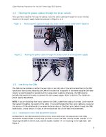
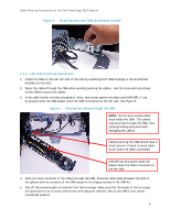
Cable Routing Procedures for the Dell PowerEdge R520 System 1.2. Routing the power cables through the strain reliefs After you have installed the tray and cables, route the power cable(s) through the strain relief(s) located on the power supply handle(s) as shown in Figures 2 & 3. Figure 2. Routing power cables through the strain reliefs on hot swap power supplies Figure 3. Routing the power cable through the strain relief on a fixed power supply 1.3. Installing the CMA The CMA can be installed on either the rear right or rear left side of the rails as described in the CMA Installation Instructions. Mounting the CMA on the side that is opposite of the power supplies (left-side mount) is recommended for systems with hot swap power supplies; otherwise, the CMA must be partially disconnected in order to remove the outer power supply. Refer to Section 2 for details on power supply replacement. NOTE: If you are installing fiber-optic cables in the CMA, a cable bend radius of at least 1 inch must be maintained throughout the length of the cable. It is recommended that fiber-optic cables be routed on the exterior of the cable bundle to increase the bend radius of the fiber-optic cables through the CMA. Additionally, a large amount of slack at the entrance and exit of the CMA is recommended. 1.3.1. Installing the inner CMA attachment bracket As described in the CMA Installation Instructions, locate and attach the appropriate inner CMA attachment bracket based on which side you wish to mount the CMA. Use the bracket marked "A" for mounting the CMA on the left side, and the bracket marked "B" for mounting on the right side. See Figure 4. 5
-
 1
1 -
 2
2 -
 3
3 -
 4
4 -
 5
5 -
 6
6 -
 7
7 -
 8
8 -
 9
9 -
 10
10 -
 11
11
 |
 |
