Dell PowerEdge PDU Metered LCD Cabling PowerEdge R520 - Page 6
Left-side mounting instructions, causing binding and potentially
 |
View all Dell PowerEdge PDU Metered LCD manuals
Add to My Manuals
Save this manual to your list of manuals |
Page 6 highlights
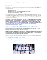
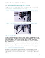
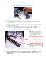
Cable Routing Procedures for the Dell PowerEdge R520 System Figure 4. Attaching the inner CMA attachment bracket 1.3.2. Left-side mounting instructions 1. Install the CMA on the rear left side of the rails by attaching both CMA housings to the attachment brackets on the rails. 2. Route the cables through the CMA while avoiding twisting the cables. Use the hook-and-loop straps on the CMA to secure the cables. 3. If the cable bundle includes a keyboard, video, and mouse system interface pod (KVM SIP), it can be placed inside the CMA basket when the CMA is mounted on the left side. See Figure 5. Figure 5. Routing the cables through the CMA NOTE: Do not store excess cable slack inside the CMA. The cables may protrude through the CMA, thus causing binding and potentially damaging the cables. Cables entering the CMA should have a small amount of slack to avoid cable strain when the CMA is extended. KVM SIP can be placed inside the basket when the CMA is mounted on the left side. 4. Once you have routed all of the cables through the CMA, dress the cable slack between the back of the system and the entrance of the CMA using the tie wraps provided in the CMA kit. 5. Clip off the excess length of material from the tie wraps. Make sure that the heads of the tie wraps are positioned so as to avoid interference with adjacent systems. Return the CMA to the closed (retracted) position. 6
-
 1
1 -
 2
2 -
 3
3 -
 4
4 -
 5
5 -
 6
6 -
 7
7 -
 8
8 -
 9
9 -
 10
10 -
 11
11
 |
 |
