Dell PowerEdge T100 Hardware Owner's Manual - Page 77
Removing a Memory Module, See
 |
View all Dell PowerEdge T100 manuals
Add to My Manuals
Save this manual to your list of manuals |
Page 77 highlights
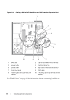
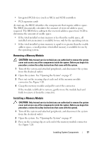
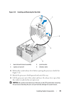
• Integrated PCI devices (such as NICs) and SCSI controllers • PCI expansion cards At start-up, the BIOS identifies the components that require address space. The BIOS dynamically calculates the amount of reserved address space required. The BIOS then subtracts the reserved address space from 8 GB to determine the amount of usable space. • If the total installed system memory is less than the usable space, all installed system memory is available for use only by the operating system. • If the total installed system memory is equal to or greater than the usable address space, a small portion of installed memory is available for use by the operating system. Removing a Memory Module CAUTION: Only trained service technicians are authorized to remove the system cover and access any of the components inside the system. Before you begin this procedure, review the safety instructions that came with the system. 1 Turn off the system and attached peripherals, and disconnect the system from the electrical outlet. 2 Open the system. See "Opening the System" on page 47. 3 Press out on the securing clip at each end of the memory module connector. See Figure 3-20. 4 Grasp the memory module and pull it out of the connector. If the module is difficult to remove, gently move the module back and forth to remove it from the connector. Installing a Memory Module CAUTION: Only trained service technicians are authorized to remove the system cover and access any of the components inside the system. Before you begin this procedure, review the safety instructions that came with the system. 1 Turn off the system and attached peripherals, and disconnect the system from the electrical outlet. 2 Open the system. See "Opening the System" on page 47. 3 Press on the securing clip at each end of the memory module connector. See Figure 3-20. Installing System Components 77
-
 1
1 -
2
-
3
-
4
-
5
-
6
-
7
-
8
-
9
-
10
-
11
-
12
-
13
-
14
-
15
-
16
-
17
-
18
-
19
-
20
-
21
-
22
-
23
-
24
-
25
-
26
-
27
-
28
-
29
-
30
-
31
-
32
-
33
-
34
-
35
-
36
-
37
-
38
-
39
-
40
-
41
-
42
-
43
-
44
-
45
-
46
-
47
-
48
-
49
-
50
-
51
-
52
-
53
-
54
-
55
-
56
-
57
-
58
-
59
-
60
-
61
-
62
-
63
-
64
-
65
-
66
-
67
-
68
-
69
-
70
-
71
-
 72
72 -
 73
73 -
 74
74 -
 75
75 -
 76
76 -
 77
77 -
 78
78 -
 79
79 -
 80
80 -
 81
81 -
 82
82 -
83
-
84
-
85
-
86
-
87
-
88
-
89
-
90
-
91
-
92
-
93
-
94
-
95
-
96
-
97
-
98
-
99
-
100
-
101
-
102
-
103
-
104
-
105
-
106
-
107
-
108
-
109
-
110
-
111
-
112
-
113
-
114
-
115
-
116
-
117
-
118
-
119
-
120
-
121
-
122
-
123
-
124
-
125
-
126
-
127
-
128
-
129
-
130
-
131
-
132
-
133
-
134
-
135
-
136
-
137
-
138
-
139
-
140
-
141
-
142
-
143
-
144
-
145
-
146
-
147
-
148
-
149
-
150
-
151
-
152
-
153
-
154
-
155
-
156
-
157
-
158
 |
 |